assembled engine
Brian Turner's custom stunt engine

Page 1 (updated 01/09/09)
Brians Skytoane

Introduction
Forward To the Index
Brian Turner, well known for the winning F2C teamrace engines that he made and competed with over the last 10 years, has recently returned to flying F2B stunt. Brian last competed in F2B back in the 70's when he was a member of the British team at the Eurochamps. Brian designed his own stunt model using the Yatsenko wing section and basic areas and moments. This model named SKYTOANE (an anagram of Yatsenko) has proved to be a capable performer and has been powered by a Stalker 61 LT LS stunt engine up to May 2008.
Brian's Stalker engines have been the subject of an extensively development program with changes to the inlet timing (changed from 56.5°/40° as delivered to 40°/45°), to the combustion chamber, the piston baffle, the crankcase volume and the addition of a plug shield. All of these changes have made these Stalkers quite competitive.
At the start of 2008 Brian decided that the Stalkers had been developed as far as possible without replacing the crankcase and other major components so he decided to make his own Longstroke 61 stunt engine based on the things that he had learnt during the development of the Stalkers. One of the main changes that has been made possible is the reduction in the height of the engine of about 3mm. This is made possible by the addoption of a backplate design that is held on with screws thus allowing a shorter conrod and the piston decending into a pocket in the backplate. This makes a considerable improvement to the crankcase compression and thus the pumping of the engine.
During the building of the first engine I loaned Brian a digital camera and he has taken pictures of all of the major machining operations.
The engine had its first outing on Sunday May 13th 2008. Brian reports that it ran well immediately with only a small tweak of the needle to get it circulating at a steady 5.5 secs/lap. Flying in a 14mph wind there was very little windup.


latest update: 24 October 2009
Index

cross section


crankcase 1 crankcase 2
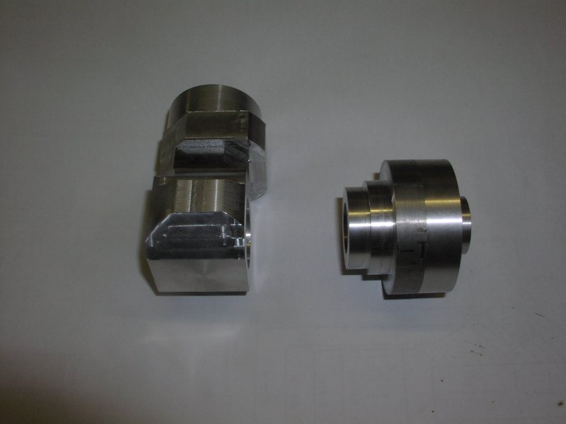
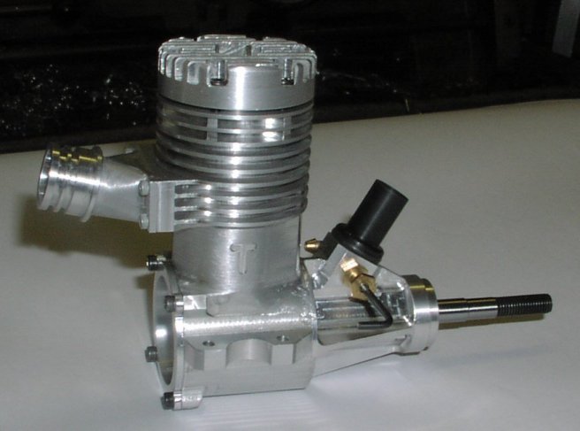
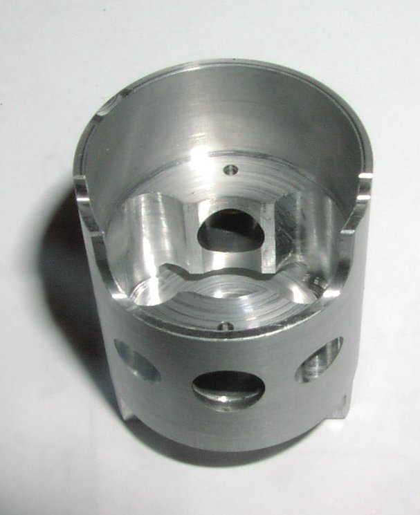
Pictures 1 & 2 crank case parts at start of picture taking - some work done
crankcase 1 crankcase 2
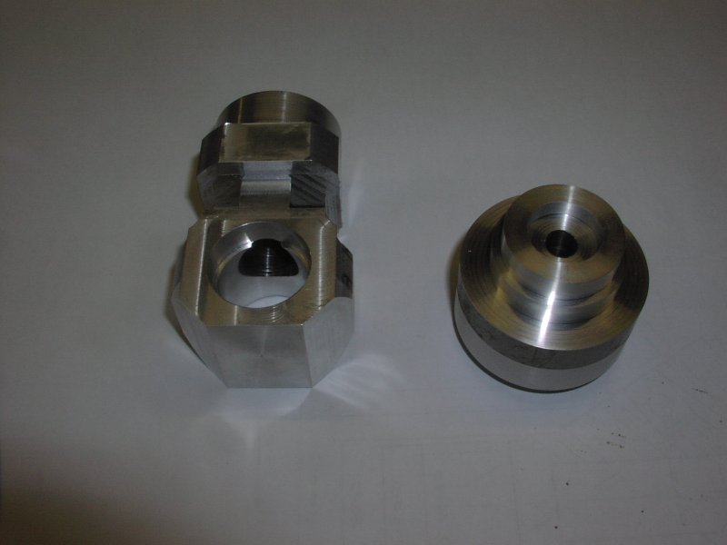
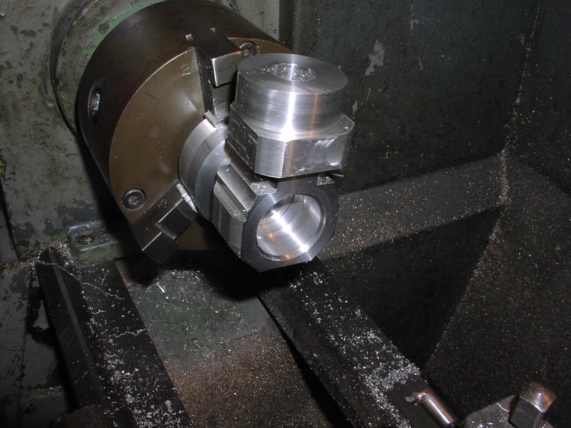
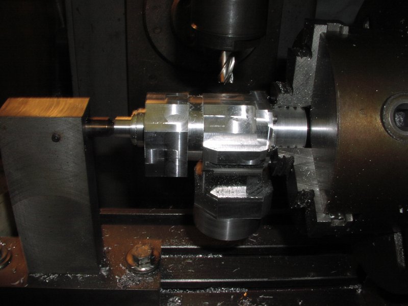
Front housing threaded and having the back ballrace and plain section machined Machining fixture for the front housing.
crankcase 1 crankcase 2
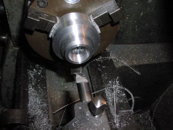
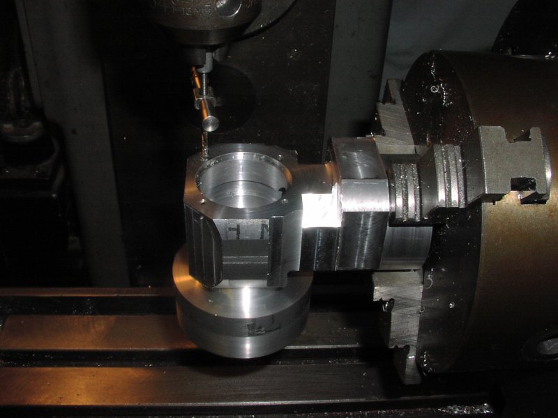
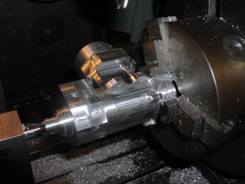
Front housing on the fixture machining the front ballrace housing and the outside nose. Machining the front face and the female thread and c/bore the main bore was machine in the milling machine with a boring head.
crankcase 1 crankcase 2
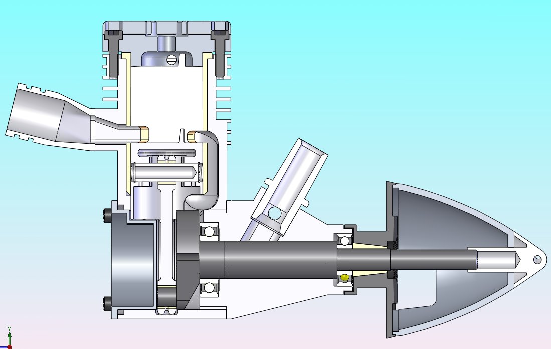
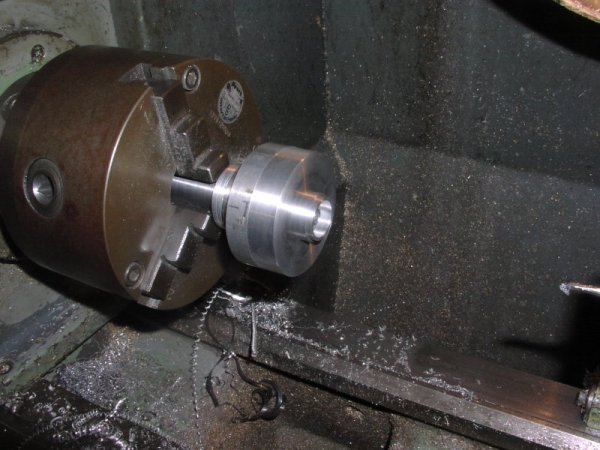
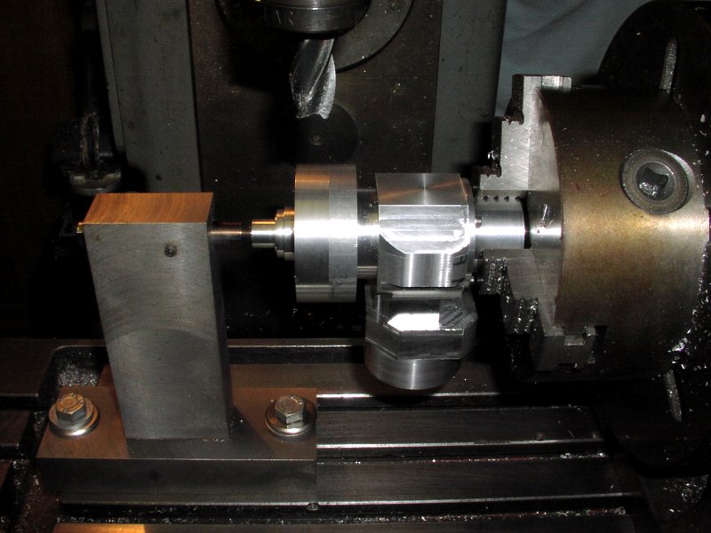
The 2 parts of the case screwed together with Loctite high temperature retaining compound.
Note: The o/d of the front housing and the front face were skimmed when the ballrace housing was being machined so that these faces could be used as a location for the next operations.
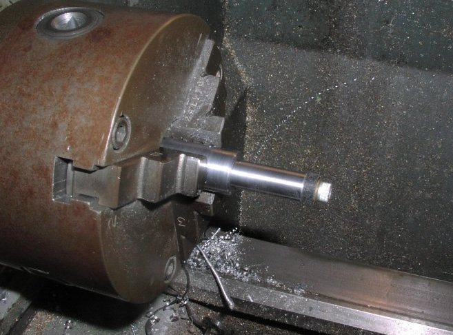
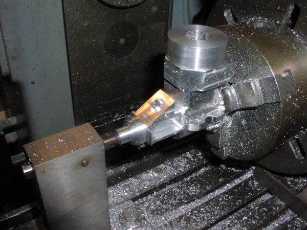
Set up to machine the back bores for the crankshaft, the clearance for the conrod, the oring c/bore on the back and face off for the backplate.
crankcase 1 crankcase 2
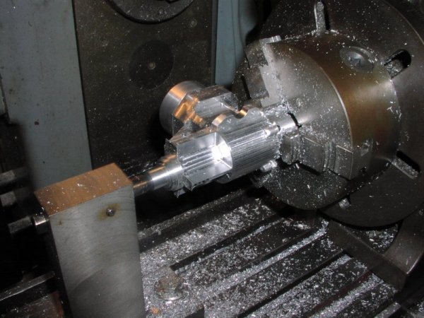
The crankcase is set up in the dividing head on the milling machine to do the backplate mounting holes as these will be needed to mount the crankcase for further machining. Again set up in the dividing head ready to rough out the crankcase and front housing the case is mounted on a false backplate and the front is supported by a accurate pin located on the front ballrace housing and the plain 12mm bore this pin will be used to dial off to do some tricky machining. later.
crankcase 1 crankcase 2
Roughing out the crankcase - the mounting lugs are taking shape and a lot of material has been removed from the case. Mounting lugs finished and the crankcase shape machined. The backplate screw lugs are machine with hand ground form tools. The mounting holes in the lugs are positioned with great accuracy as they become the main location for the machining of the inside of the upper crankcase.
crankcase 1 crankcase 2
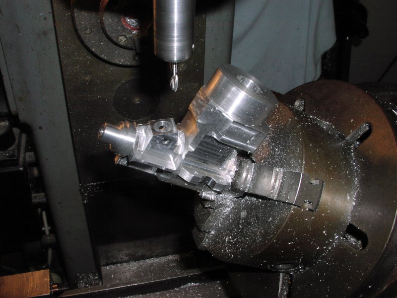
The front housing webs are machined to thickness but left full width to use as datums later. Next the spraybar hole is drilled then the venturie top surface is machined with the dividing head tilted to 30° the venturi hole is machined relative to the spraybar hole by putting a pin through it and wobbling off it. Finishing the webs and removing anything that doesn't look like a stunt engine.
crankcase 1 crankcase 2
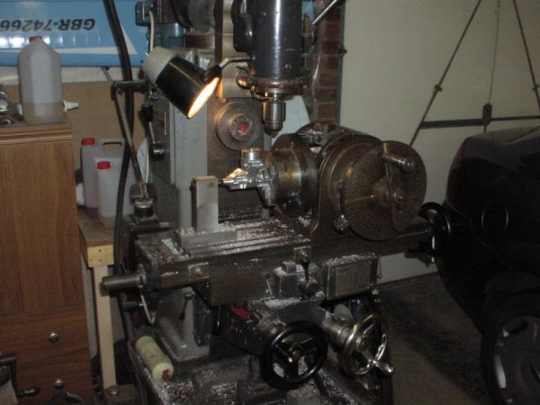
The milling machine - no digital readout need apply - the dividing head is a proper solid tool. More venturie internal and external machining.
Next Page
© 2008 Mike Nelson. All rights reserved.

This description has been put together by Mike Nelson using pictures taken by Brian
Go back to Mike Nelsons controline Home Page Go back to Mike Nelsons Home Page

This site is created and maintained by Mike Nelson for his own pleasure