Page 6 (updated 01/09/09)
|
Page 6 (updated 01/09/09) |
|
 |
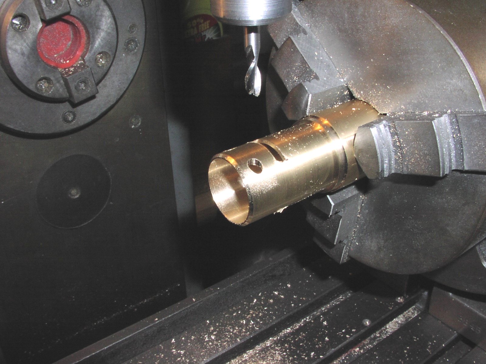 |
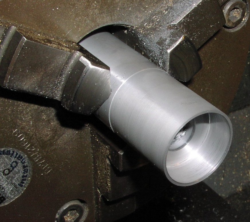
| Machine outside diameters and tapered inside diameters from CZ121 brass rod. | Mill ports into the liner using the dividing head. |
 |
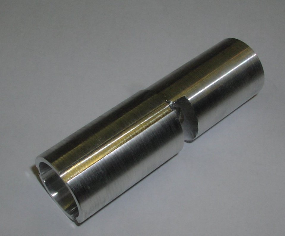 |
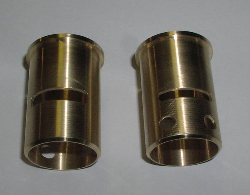
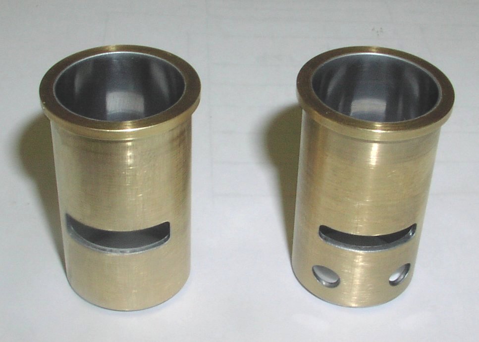
| Finished machined liners. | Flexable tapered lap made from aluminimum alloy HE30. |
 |
 |
|
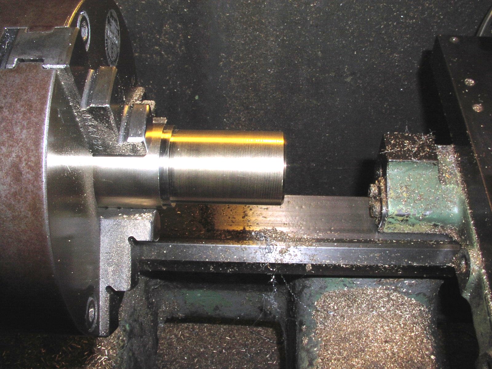
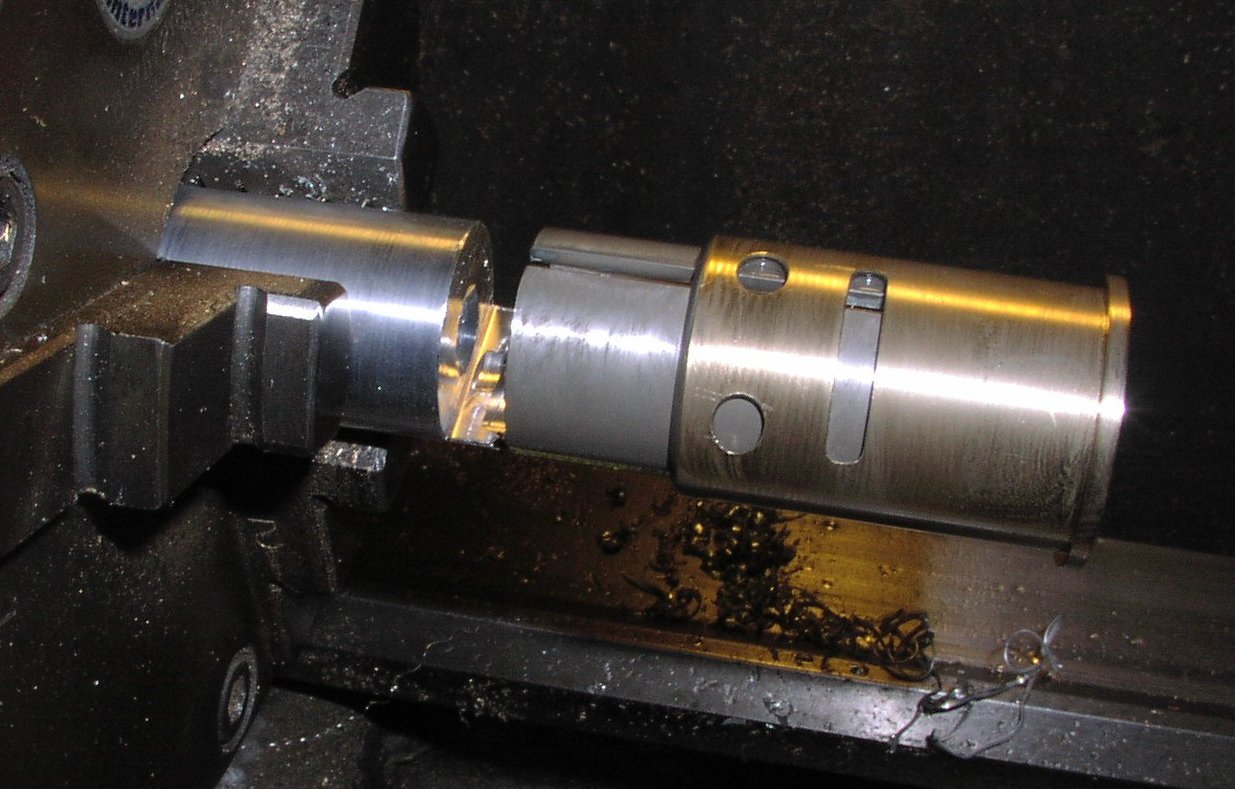
Lapping the liner to remove machining marks and give a true surface ready for chrome plating. Mount the lap in the lathe and, using grade 1000 carborundum powder with a little oil, lap at about 80 R.P.M. until all machining marks are removed. If necessary press a small piece of soft rubber into the split of the lap to maintain pressure |
Liners ready for chroming |
 |
 |
|
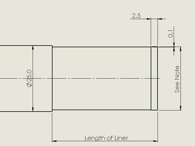
A simple but effective method of measuring the taper and shape of the bore is as follows:- Machine the end of a 1" diameter aluminimum alloy rod until it just fits into the bottom of the liner (2mm to 3mm). Undercut this diameter by 0.1mm deep to the length of the liner as shown in the drawing. From this information you can also decide the fit of the piston. Many people would say that the lapping and the measuring of the bore are over kill and they could be right! |
 |
Liners now finish chromed. The chroming was done by Yakov Mazniak of Kharkov, Ukraine. The bores have been ground (also by Mazniak)and honed with a taper of 0.089mm (0.0035")top to bottom. |
 |
 |
|
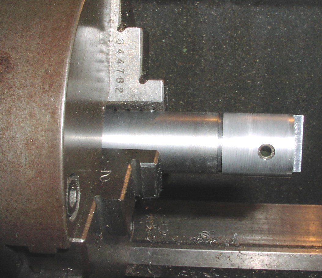
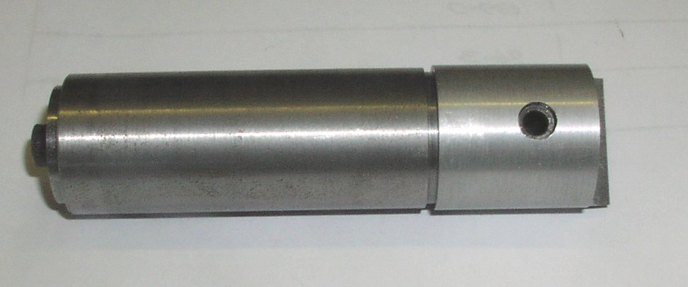
The piston is manufactured from 20% silicon powder metal See page 8 for source. This material is best machined with a tungston carbide turning tool resharpened to give a 10° toprake and a very sharp cutting edge This is very important as the silicone in the piston will wear the tool very quickly and a new "as purchased" turning tip will not give the required finish. A serious manufacturer would use a diamond turning tool. Machine the inside diameters to final size and machine the outside diameter to 0.2mm (0.008") above nominal dimension. |
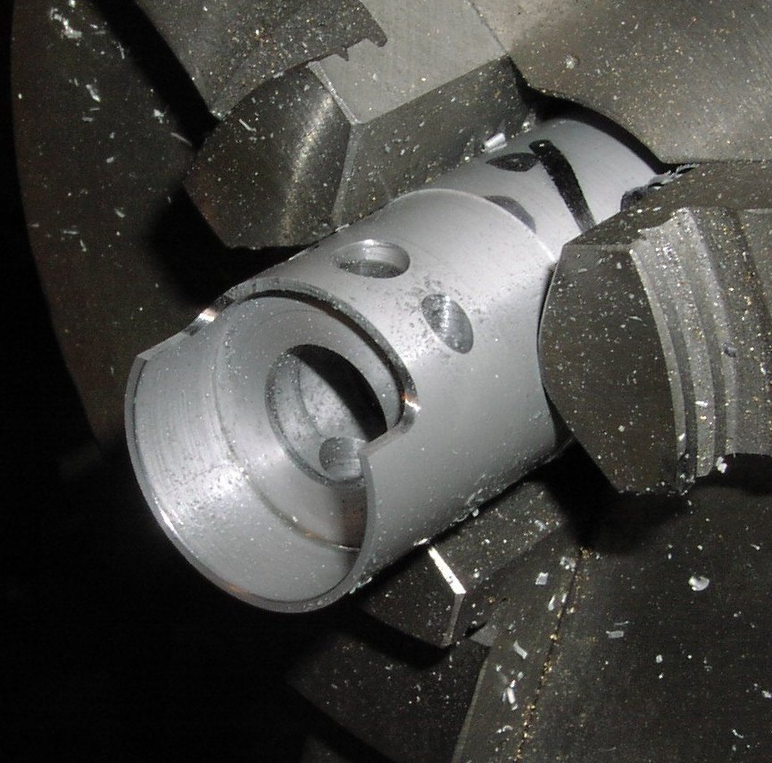
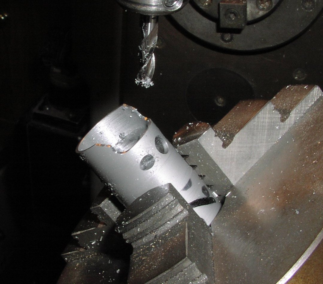
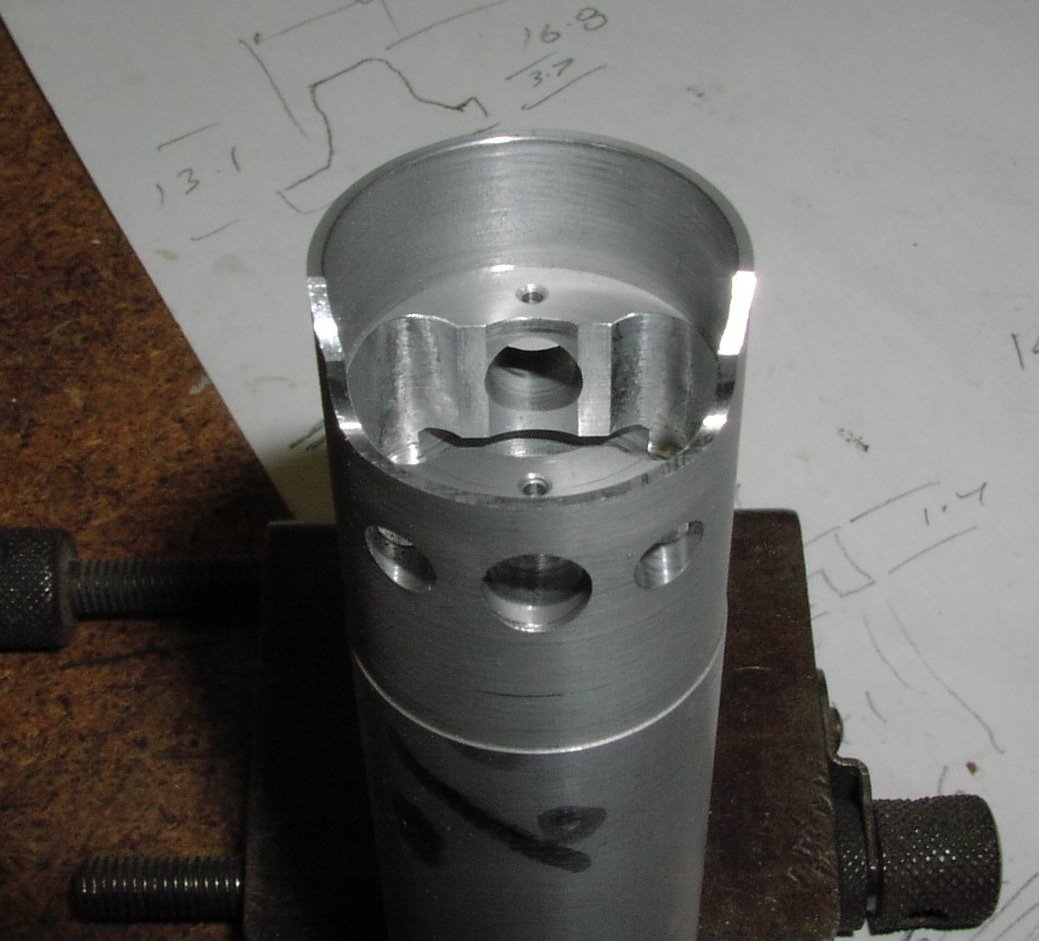
Transfering the rod to the dividing head on the milling machine drill and ream the gudgeon pin hole (wrist pin in the US). Mill the piston ports and the skirt cutout. |
 |
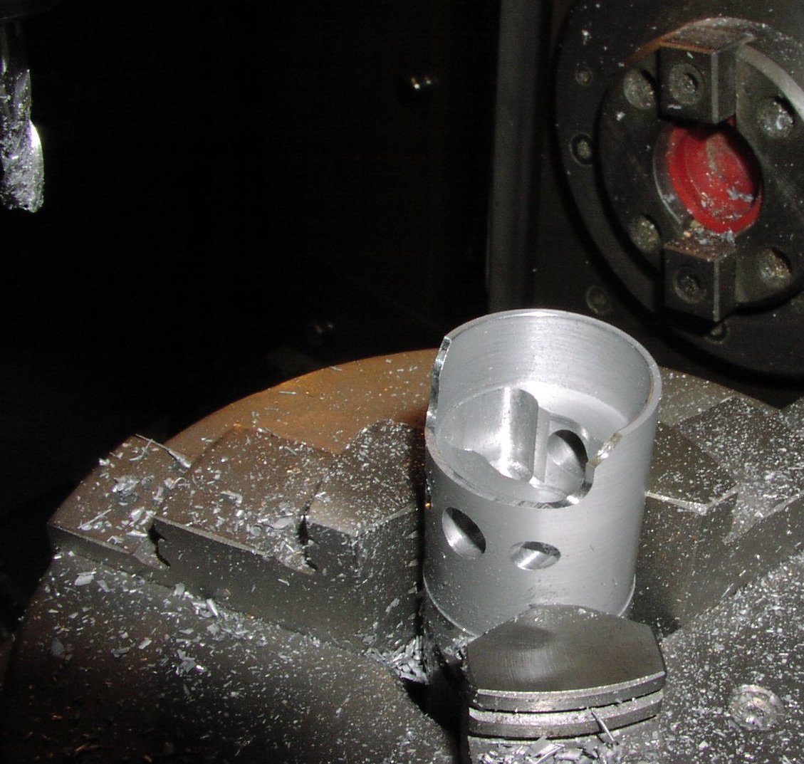 |
| Machine the chanfer on the corner of the cutout in the piston (this is to ensure that the piston misses the bearing housing at the bottom of its stroke. | mill the inside of the piston. |
 |
 |
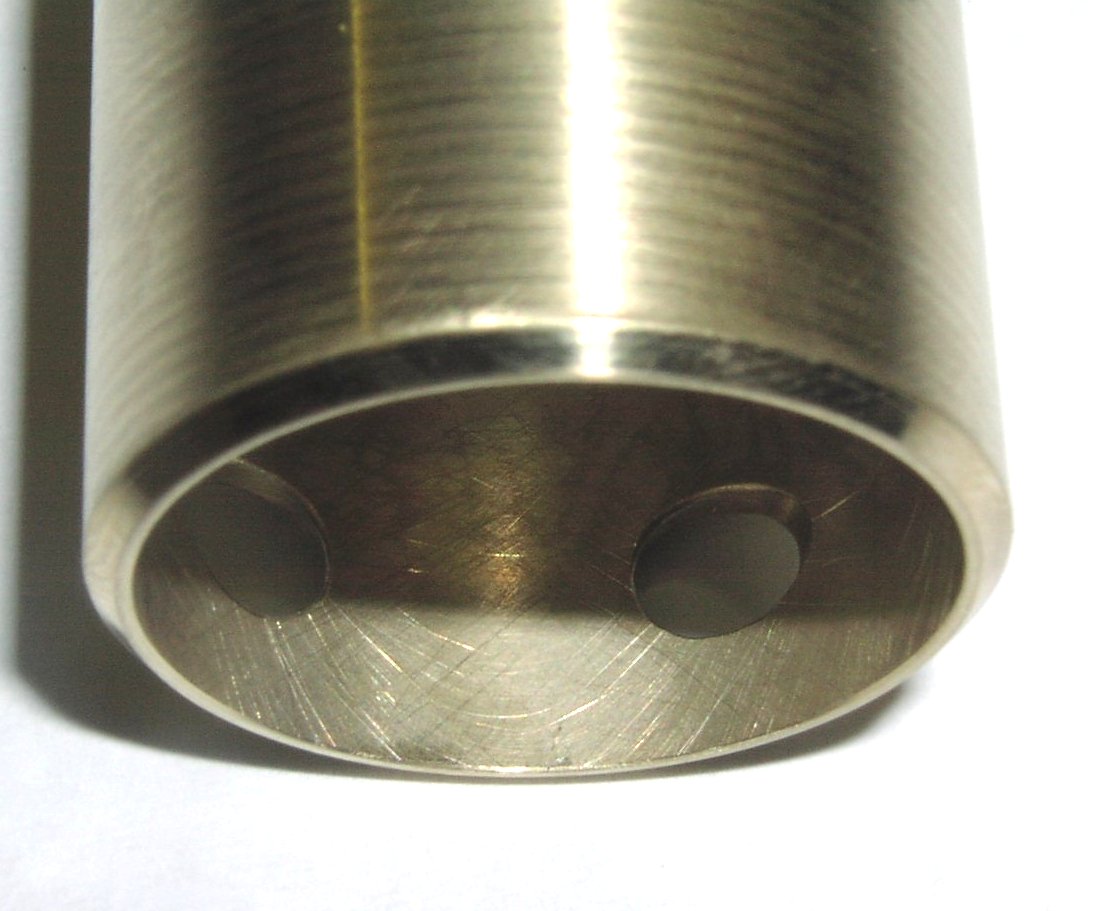
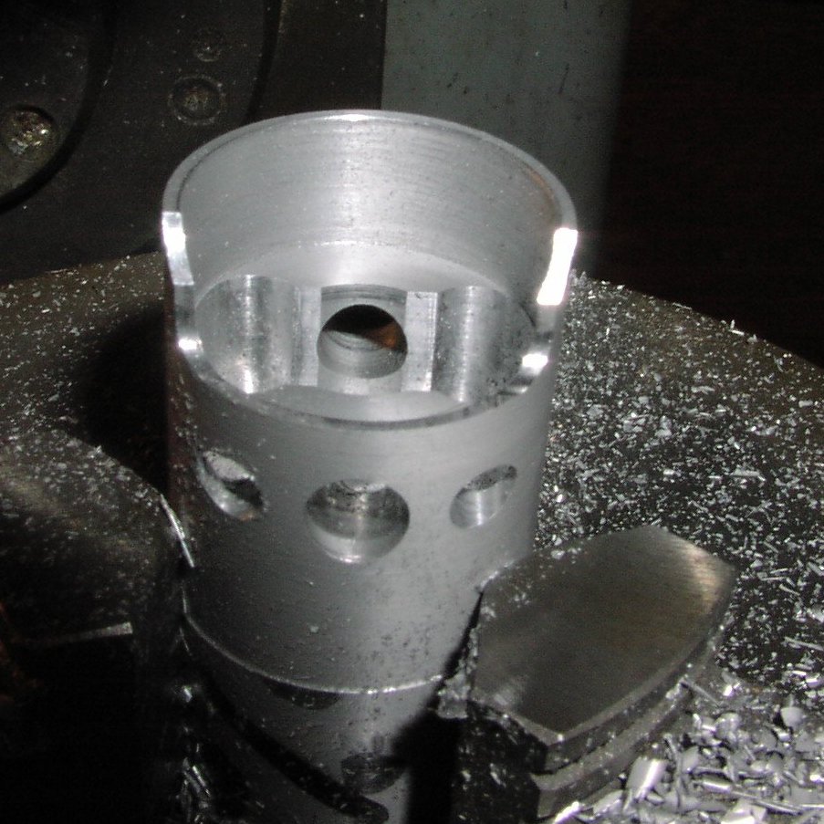
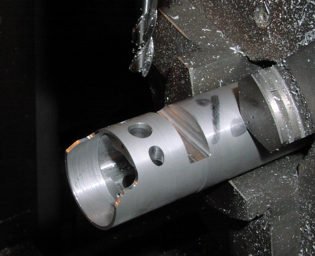
| Mill the inside of the piston. | Showing the undercut under the gudgeon pin boss and the 2 lubrication holes. |
 |
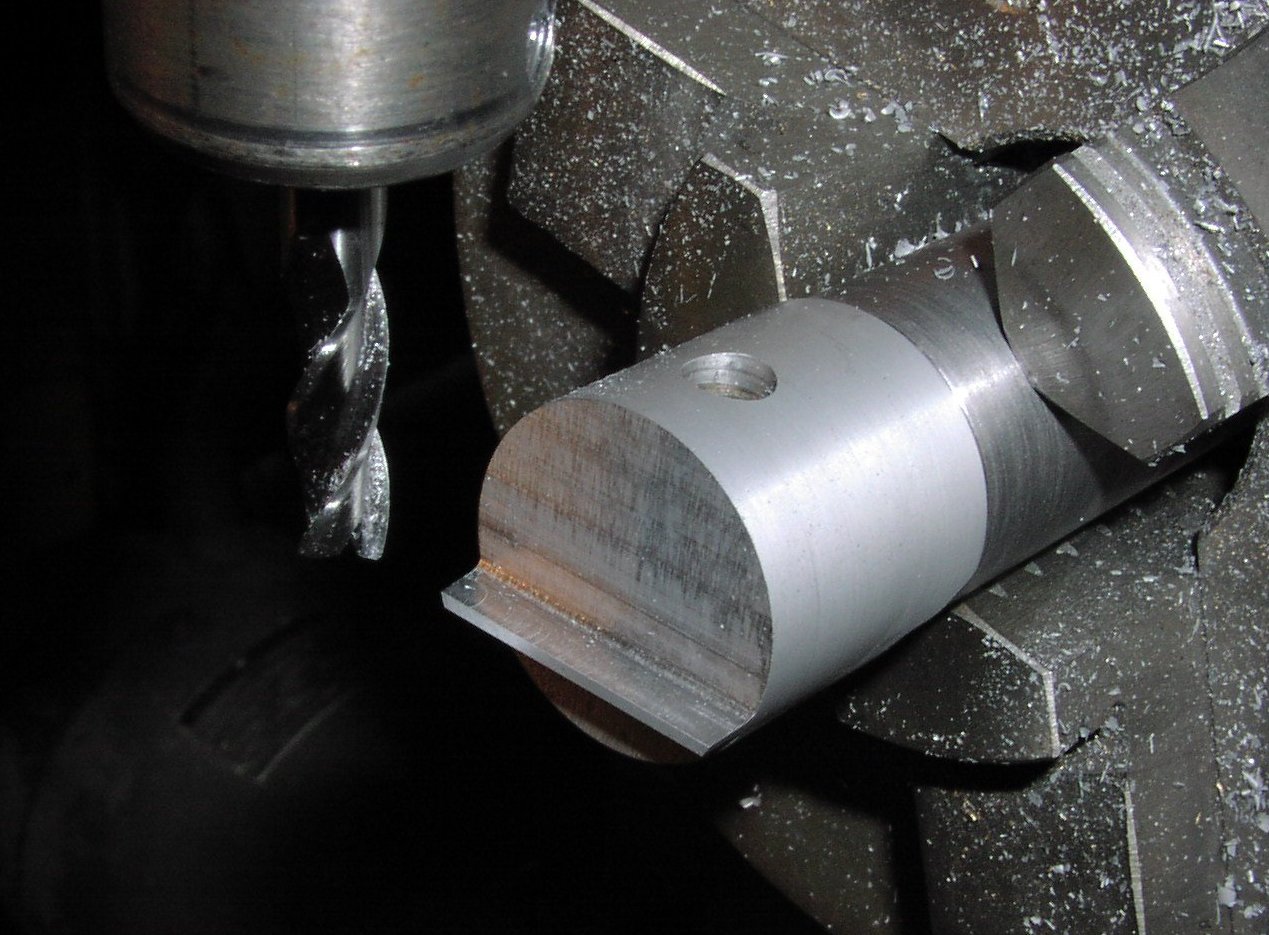 |
| Machine one side of the piston up to the baffle then part off the piston from the rod. | Mount the piston on the location fixture (the one that will be used for lapping the piston) and machine the other side of the baffle. |
 |
 |
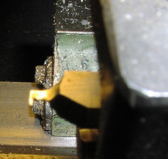 |
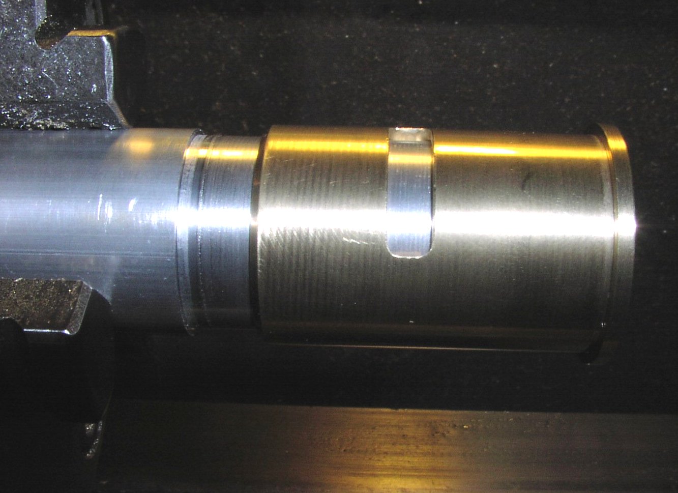
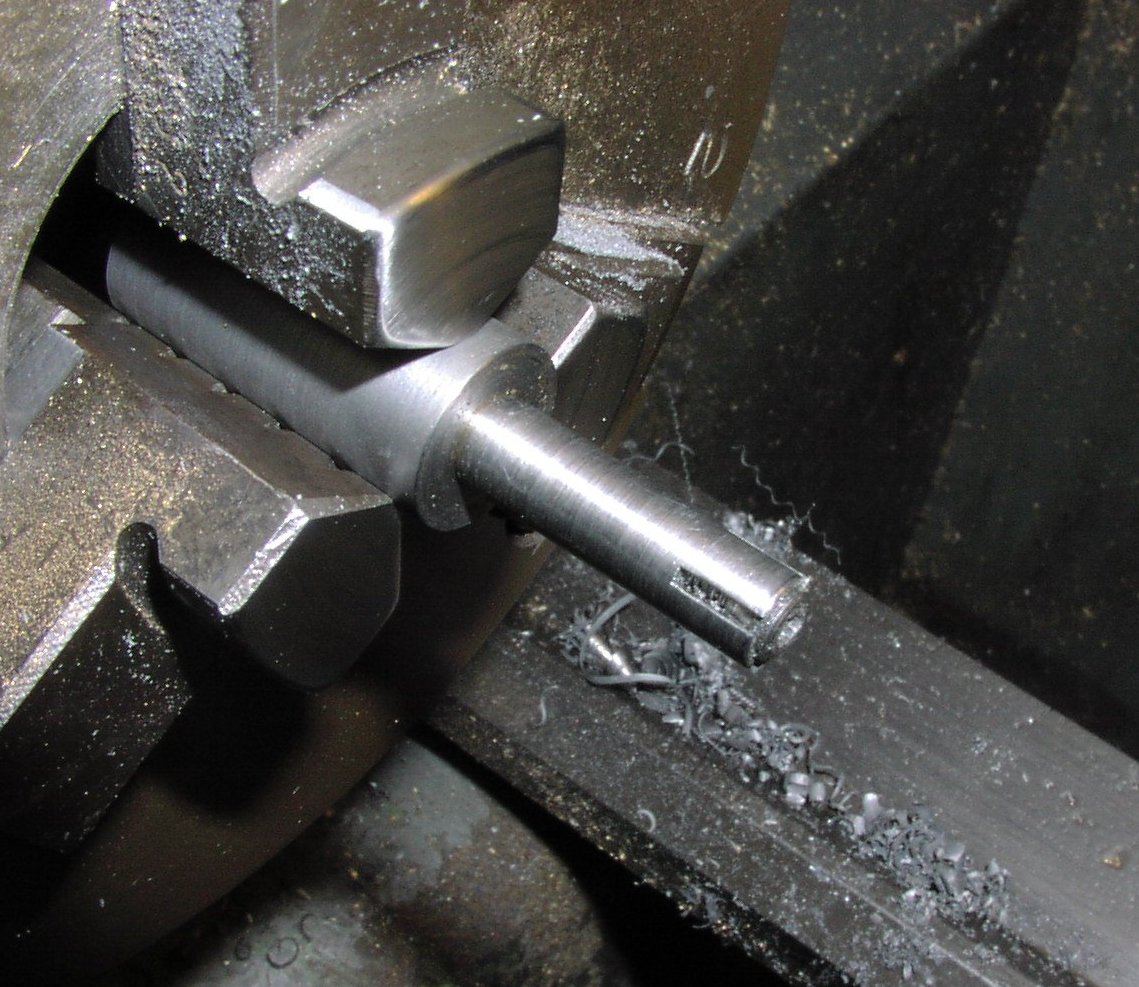
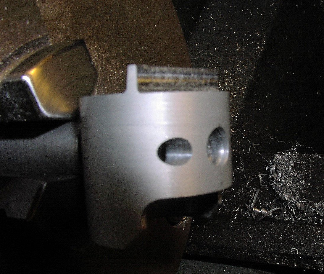
| The piston is mounted on this expanding mandrel in the lathe to machine the circlip grooves | The piston is slid onto the mandrel and the tapered screw tightened to grip the reamed hole. | the groove is machined with this tiny grooving tool. |
 |
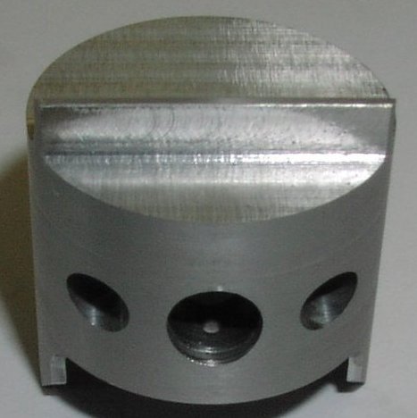 |
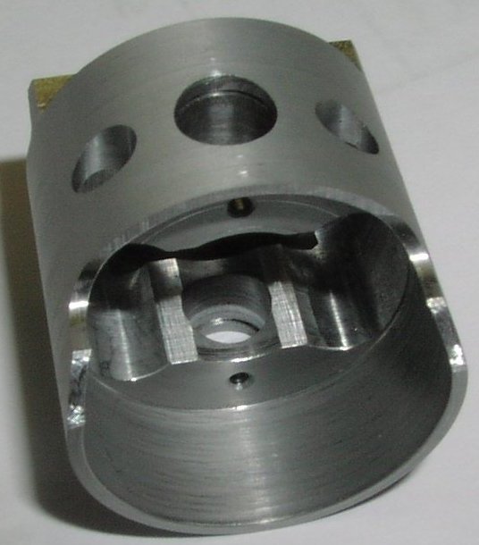
| Inside of finished piston | Top of finished piston |
 |
 |
|
A decision must be made at this stage on the piston fit in the liner. in this instance I wanted the finished piston to interfere (start to bind in the liner) at 2.5mm (0.1") from top dead centre. The liner has been measured and the taper is known so the actual diameter of the piston can be calculated. On this engine the piston is 5mm (0.197") from the top of the liner at top dead centre, so the fit required is 7.5mm (0.295") from TDC. The piston is turned to 0.012mm (0.0005") oversize. Then the 0.75° taper is machined around the top of the piston including the baffle. The taper is machined so that after final lapping the width of the taper will be 2mm (0.080")approx. The cleaned liner is put over the piston and slid down until the piston just binds. This depth is measured with a depth gauge and the result noted. The piston is now lapped to the final diameter using the lapping tool shown on page 8 with 1000 grit carborundum mixed in engine oil. The lap is set to size by placing it over the piston and tightening the clamp screw until it is just free. A tiny amount of the grinding past is then dabbed onto the piston and the lap is put over the piston with the lathe stationary. The lathe is then started at about 50RPM and the lap is held and moved bacwards and forwards a few times (about 4 times) the lap is then removed, turned round and a 4 passes made. The lap is then removed and the piston cleaned with a solvent and dried carefully. The clean and dry liner is then put over the piston until it just binds and the depth from the top of the liner to the top of the piston is again measured with a depth gauge. This will give an indication of how much lapping is required to move the piston up the bore to the required position. The proceedure is repeated. The lap is reset each time by putting onto the piston and tightening the clamp screw till it just starts to drag. A tiny amount of new grinding compound is added each time. This is repeated until the required fit is achieved. Note: when removing the lap is should be done in a swift move whilst the lathe is running or it may bind. This proceedure sounds laborious but is actually quite straight forward in practice. Fitting the piston to the new engine took only about 1 hour and the lapping took only 10mins. The piston and liner must now be thouroughly cleaned. This is done using washing up liquid and an old toothbrush in hot water. All vestages of the lapping compound must be removed. The piston fit achieved by this method will not need any significent running in. The first engine had only 15mins on the bench before flying in the aeroplane. |