Page 2
|
Page 2 |
|
 |
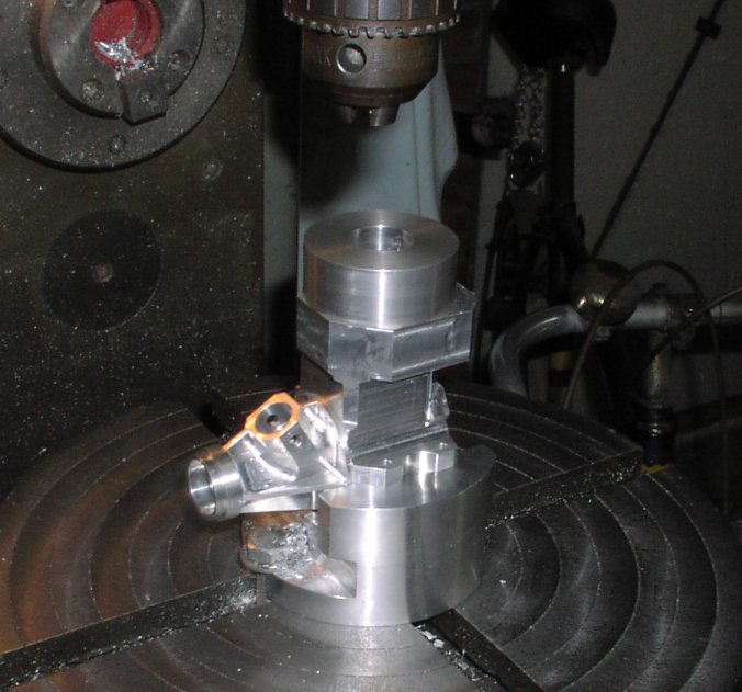 |
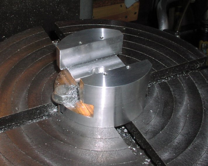
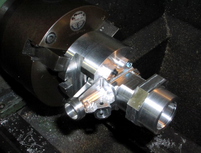
| Now Brian is ready to machine the cylinder internal and external diameters. This is the fixture Brian has made to mount the crankcase both on a rotary table and in the chuck of the lathe. The fixture has a spigot locating in the centre hole of the rotary table. This rotary table is a very old but well made unit that has seen a lot of use and was showing the scars. Brian has skimmed the surface of the table and also remachined the centre hole to get the accuracy he demands. | The engine is just standing in the fixture showing showing where it will fit when it is returned to the Miller after the machining of the internal bores that is the next operation. |
 |
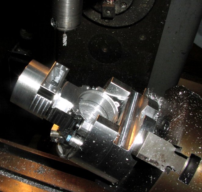 |
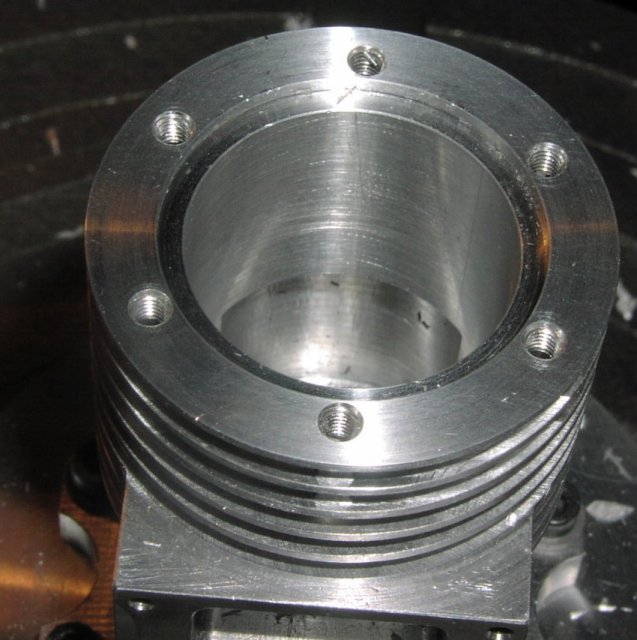
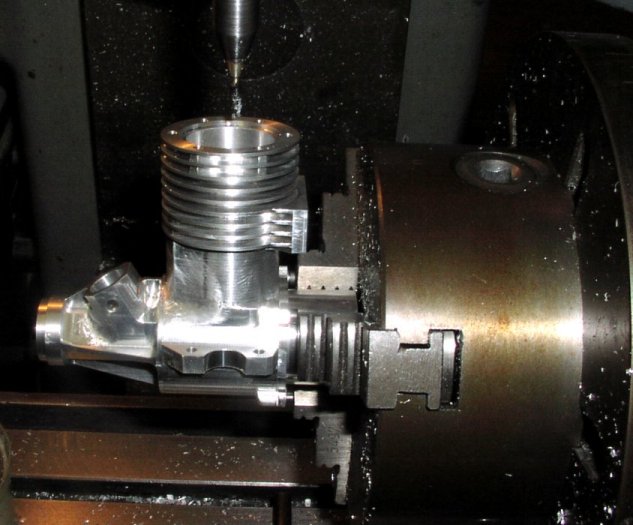
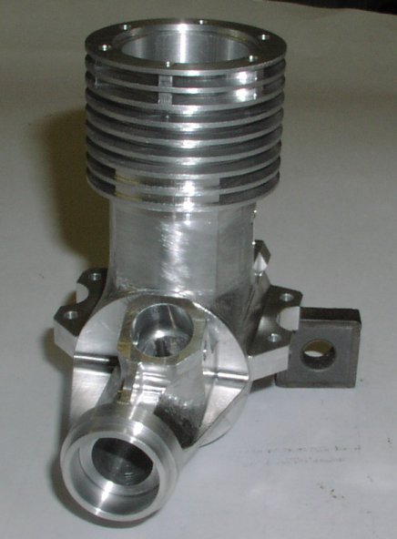
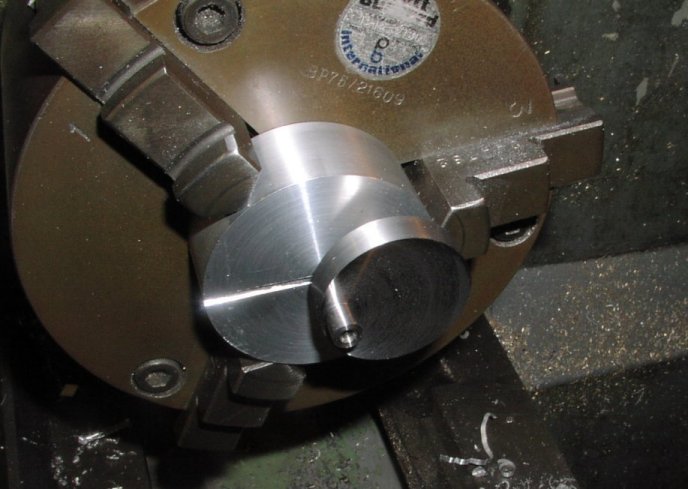
| The same fixture is fitted to the lathe so that the round parts of the cylinder can be machined. As shown here the internal bores are finished and the transfer port outside shape has been turned (the front part of the crankcase behind the venturi). | The exhaust port has been machined on the outside with the dividing head horizontal. Now the head has been tilted up to finish off the internal exhaust port machining (the upper face). |
 |
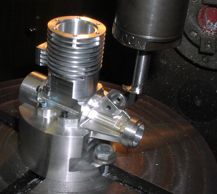 |
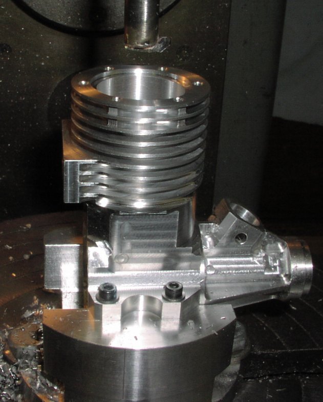
| The case is now on the fixture mounted on the circular table and the fins are being machined. The tool is specially made for this engine to get the correct radius. Note it worked best when climb milling and all the slots were cut to depth in a single cut. This gave the best finish and the least chatter. Another trick Brian has used is to fit the dummy backplate fixture to the case to give even more stiffness to the case whilst machining. |
 |
 |
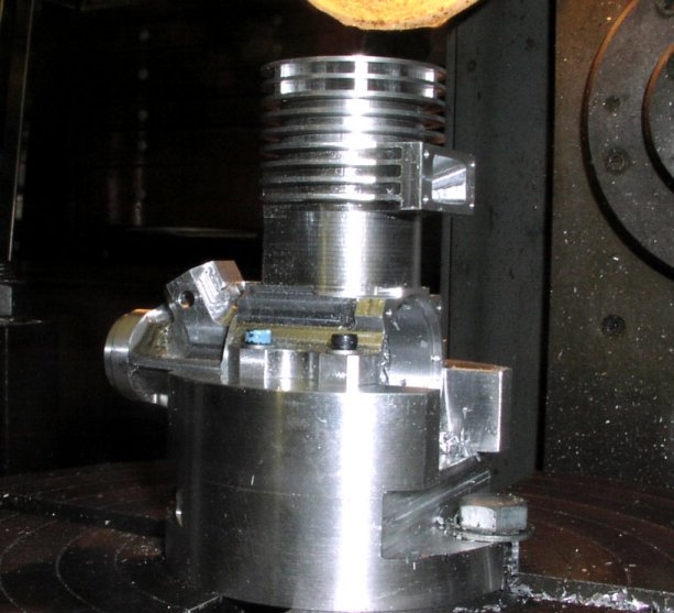
| Machining the transfer port. This is the tool that Brian used - a single point tool with the largest shank that will allow the radius required for the internal port. |
 |
 |
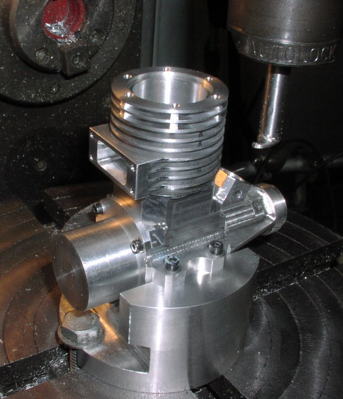
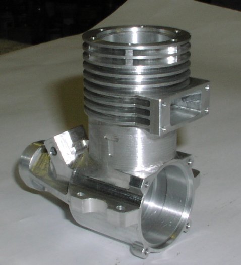
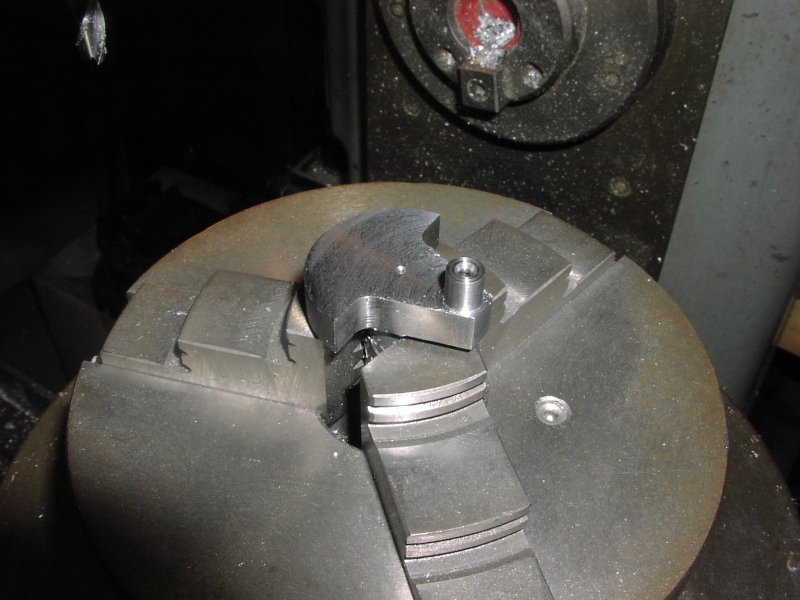
| The outside of the case below the exhaust port is now machined. | The conrod clearance groove has been machined by rotating the case and using another Brian's custom tools. |
 |
 |
 |
 |
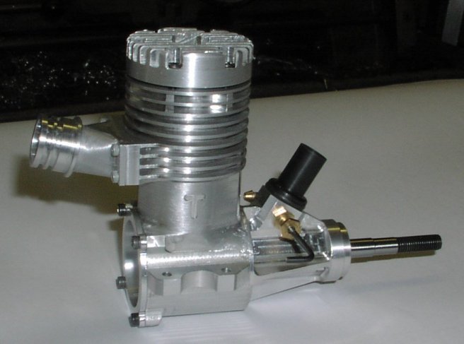
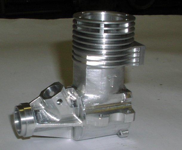
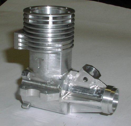
| The case is now finished and any of the little hand fettled areas where machining is impossible have been dremel'd. |
 |
 |
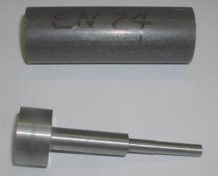
| The crankshaft is made from a piece of EN24 A hardening carbon steel. as shown here the billet has been roughed out to plus 1mm all over to allow for any movement in the steel. (EN24 is a high quality, high tensile, alloy steel . Usually supplied readily machineable in ‘T’ condition, it combines high tensile strength, shock resistance, good ductility and resistance to wear). | The roughed out shaft now has a centre in the end and is turned to plus 0.3mm ready for hardening. |
 |
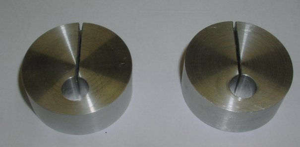 |
| This is the machining of the 2 fixtures needed for machining the crank pin. There are two fixtures as the shaft mounting holes are different sizes. One is used for the machining when the shaft is plus 0.3mm and one for when the shaft is at the final size. The two are made from a single piece of aluminium and parted off when finished thus ensuring that the offsets are identical. |
 |
 |
| Using the roughing fixture for machining the pin. | Machining the crankshaft web. The crankshaft is fitted to the dividing head for this job and the horizontal flats are machined accurately to use as datums for setting up the shaft for the next operations. |
 |
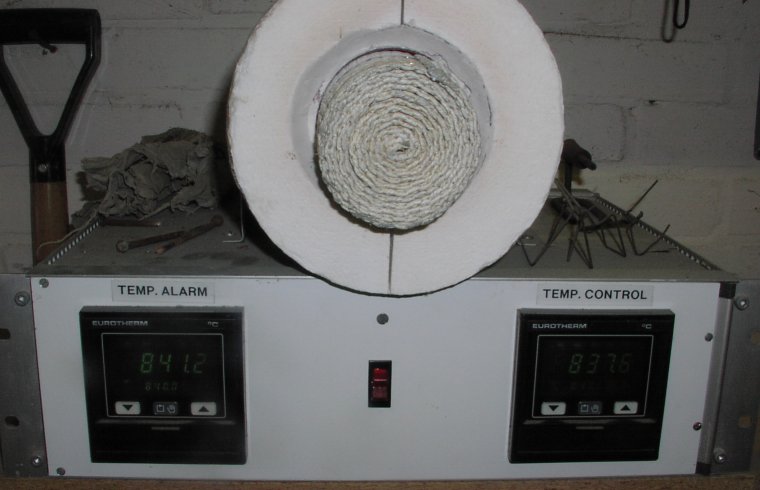 |
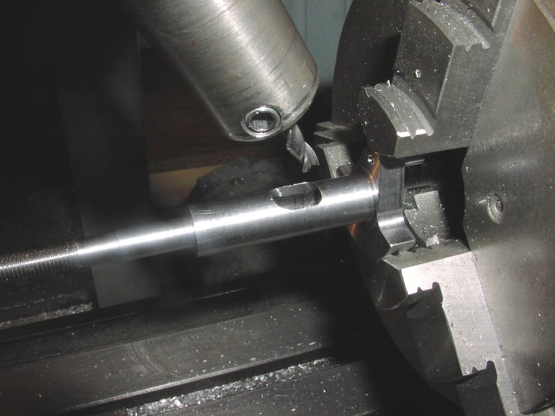
| Machining the inlet port in the crankshaft. The bore has been drilled previously. The machining is done with the milling machine head set over at 30° so that the crankshaft is parallel to the bed enabling the crankshaft to be supported with a centre (not shown). | This is Brian's home made muffle furnace that he uses for all his heat treatment. it should be capable of working up to 1000°C. The shaft was heated to 840°C then quenched in oil. Tempered to 180°C and quenched in oil. |
 |
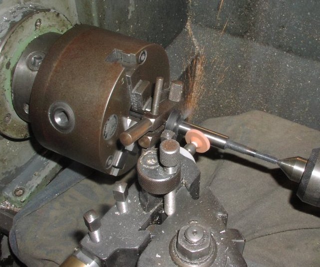 |
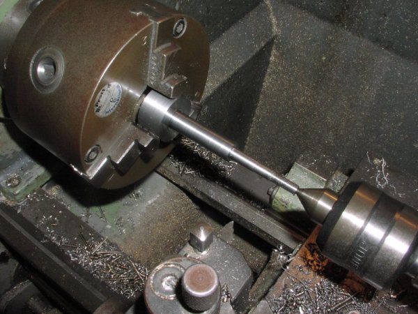
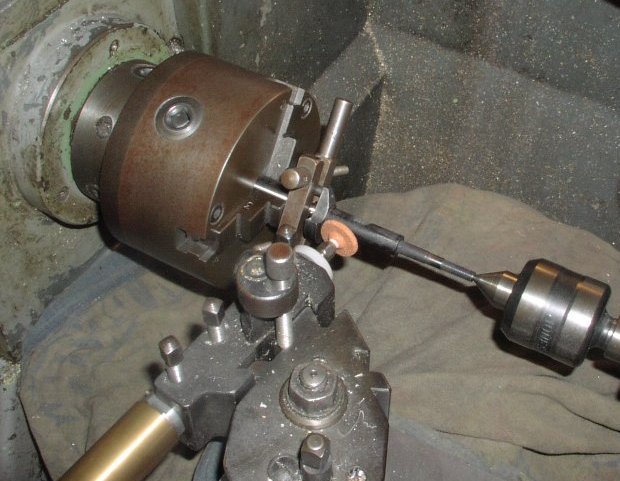
| The shaft is set up in the lathe for the final grinding to final size. The power is a Dremel driving a custom made toolpost grinder. |
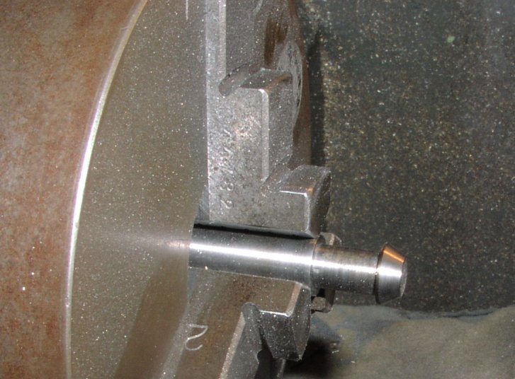 |
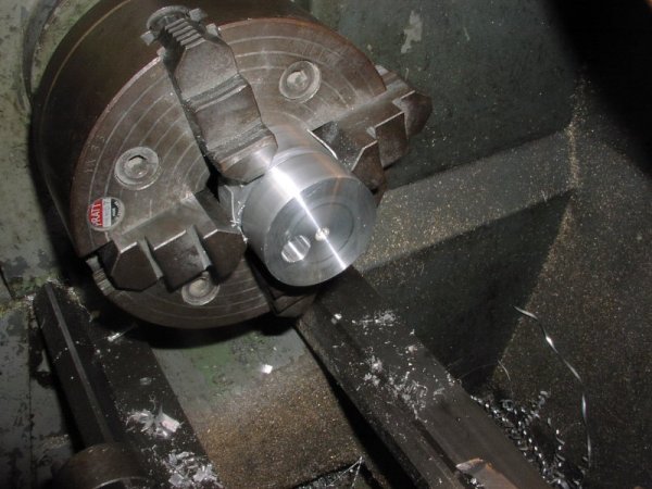
| This is the centre pin in the chuck used for mounting the shaft turned to allow the driving dog to clamp on it and the crankpin. |