This is page 3 of the design and detailing blog for the recreation of the 1898 Baldwin narrow gauge locomotive known as LYN. The work on this project started at the begining of 2011 and to see the blog of the work during 2011 and 2012 please go to page one. to see the work during 2013, and 2014 please go to page two.
For the current Status of the Detail Design and Drafting (02/11/2015) please go here
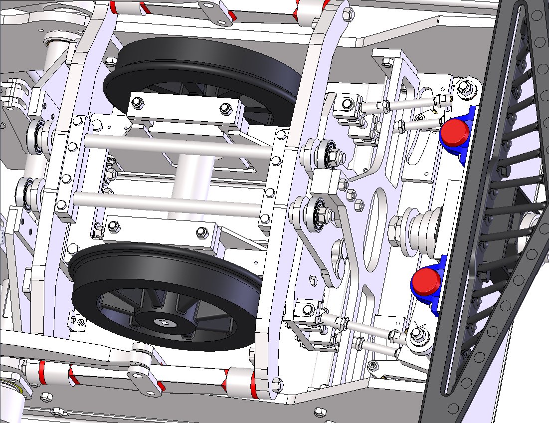
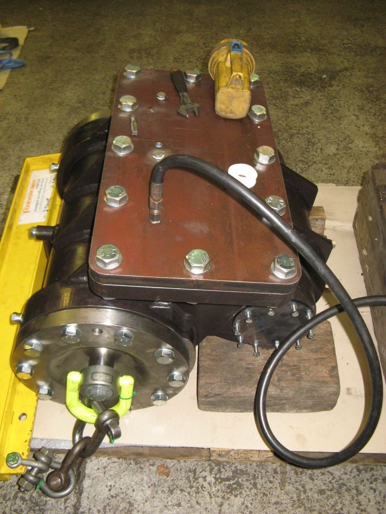
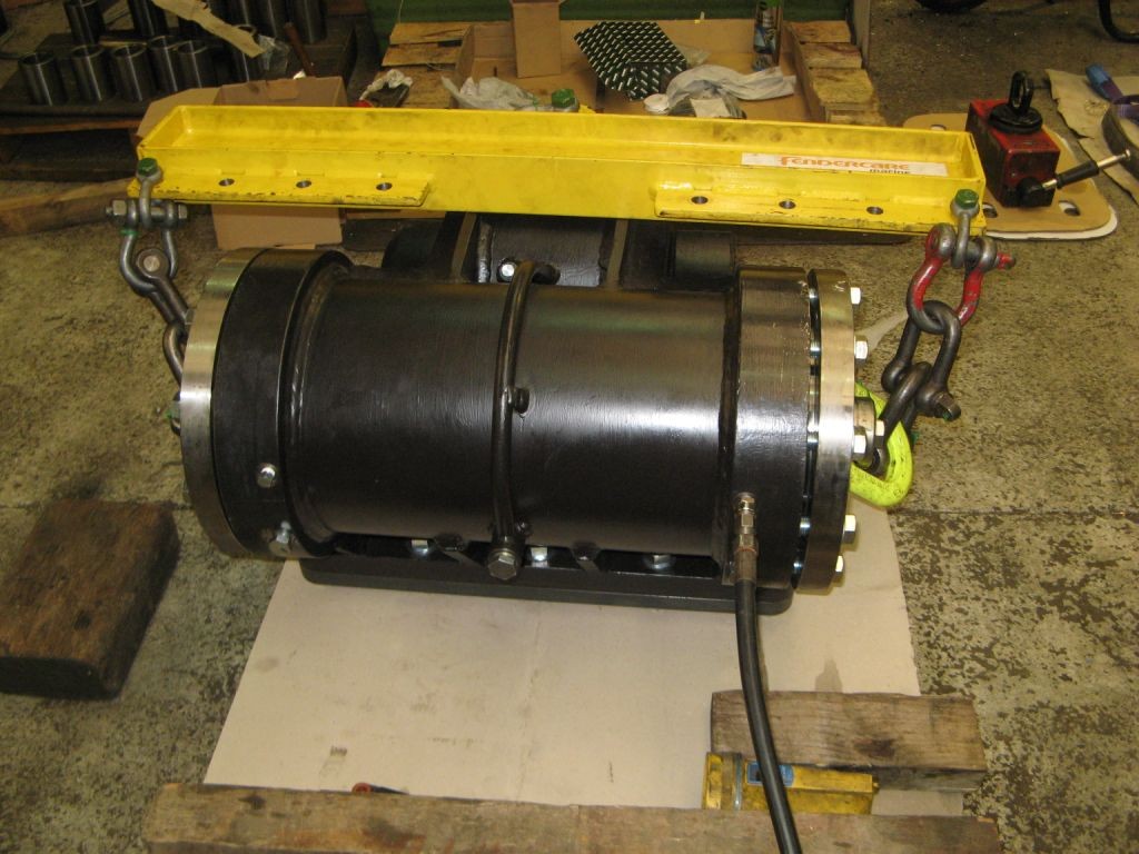
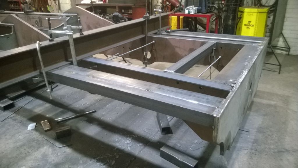
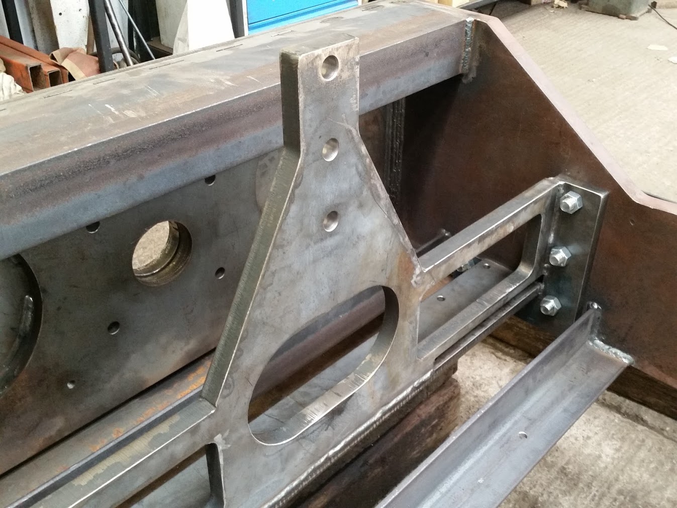
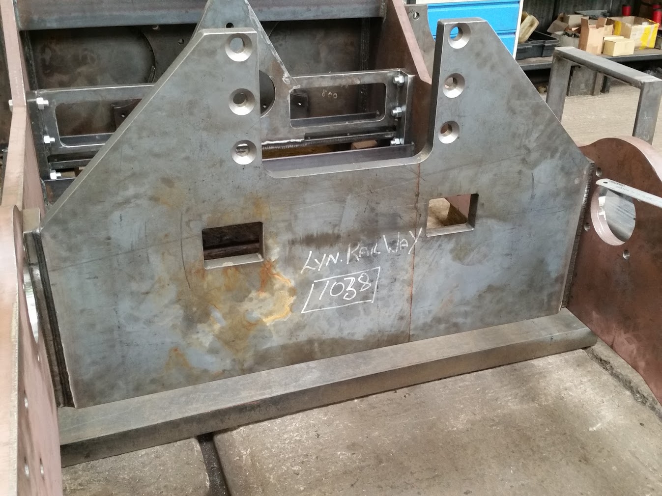
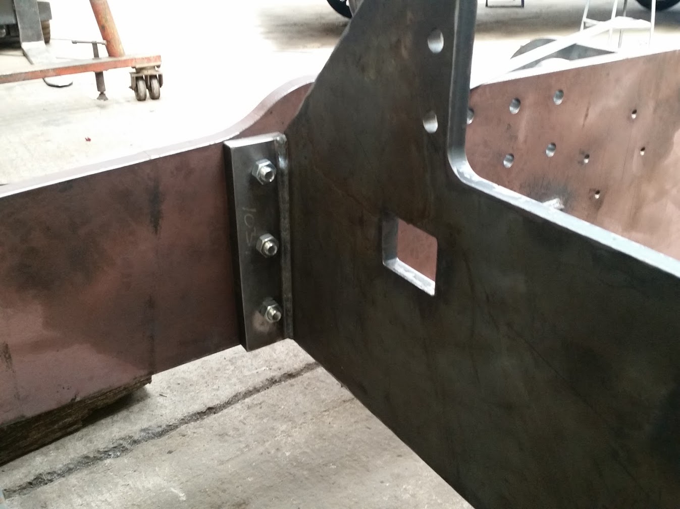
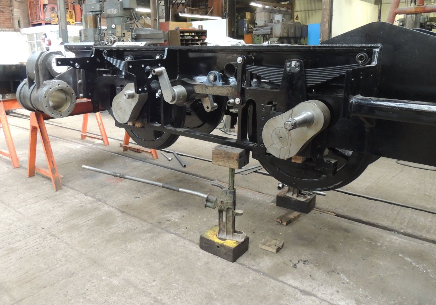
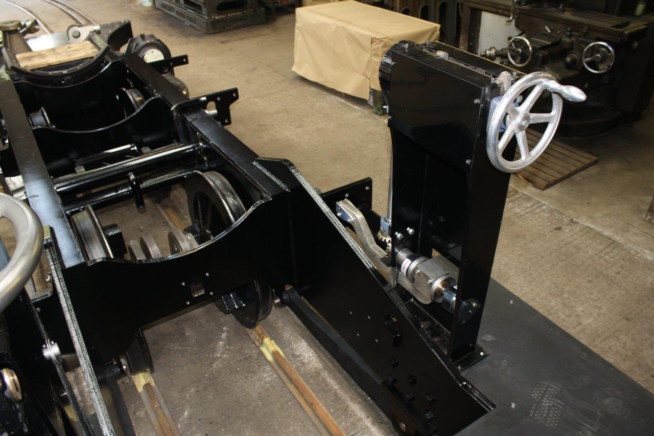
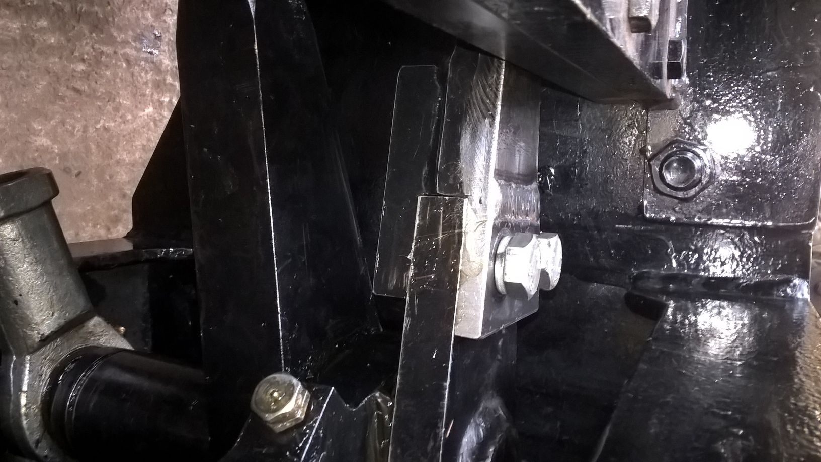
the braking system is now well advanced and I am about halfway through the task of producing the drawing for it. Here is a first picture of the braking assembly fitted to the frame
This is the braking assembly fitted to the loco chassis.
Modelling progress up to 24th February 2015
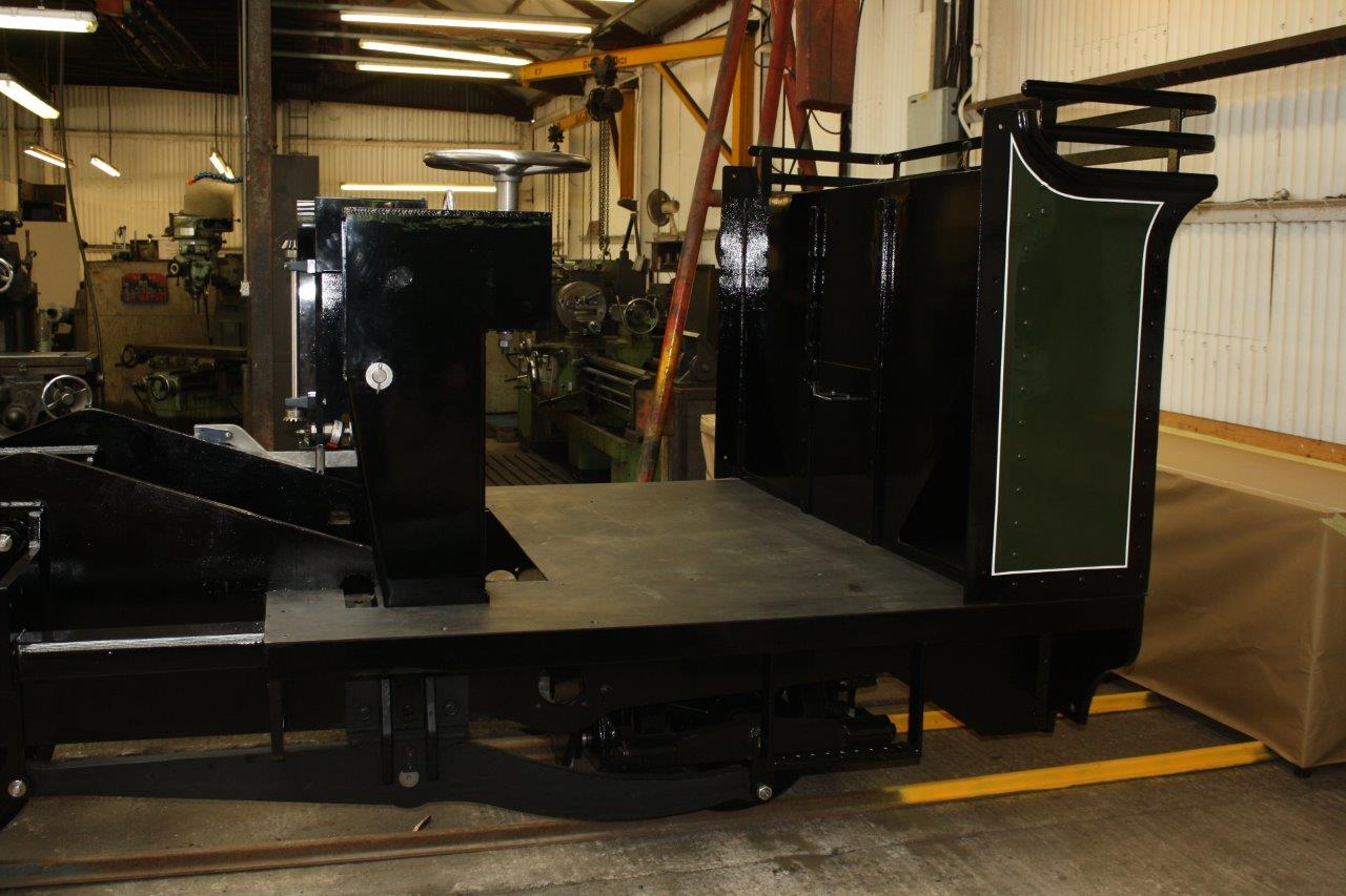
The modelling of the braking system is now complete and the detail drawings are started. The cab footplate design has been completed by Ian and I have started creating the models and adding it to the main model assembly.
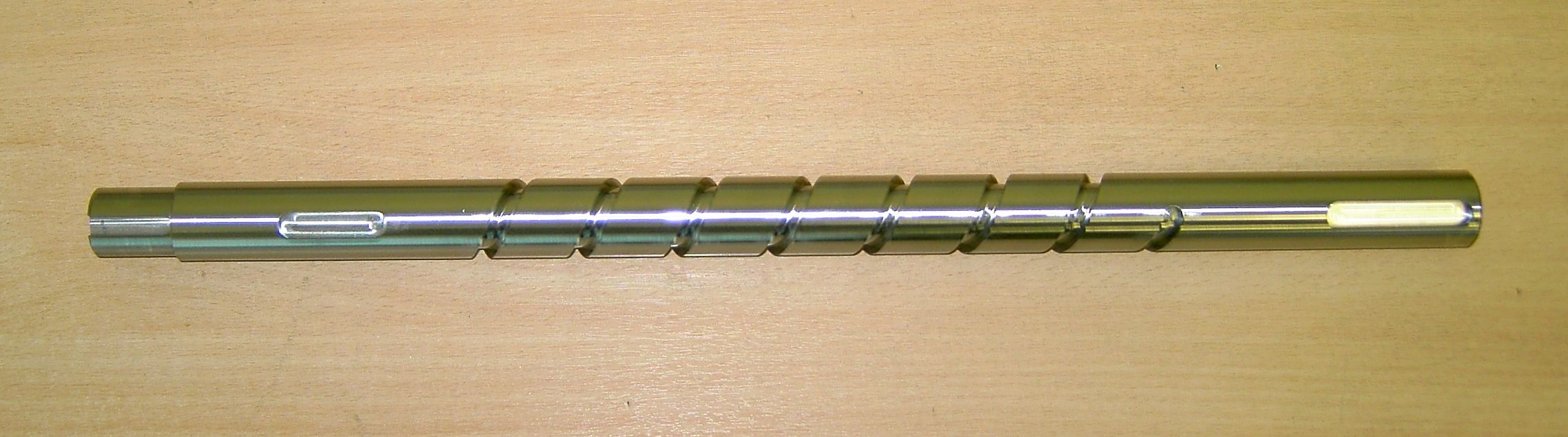
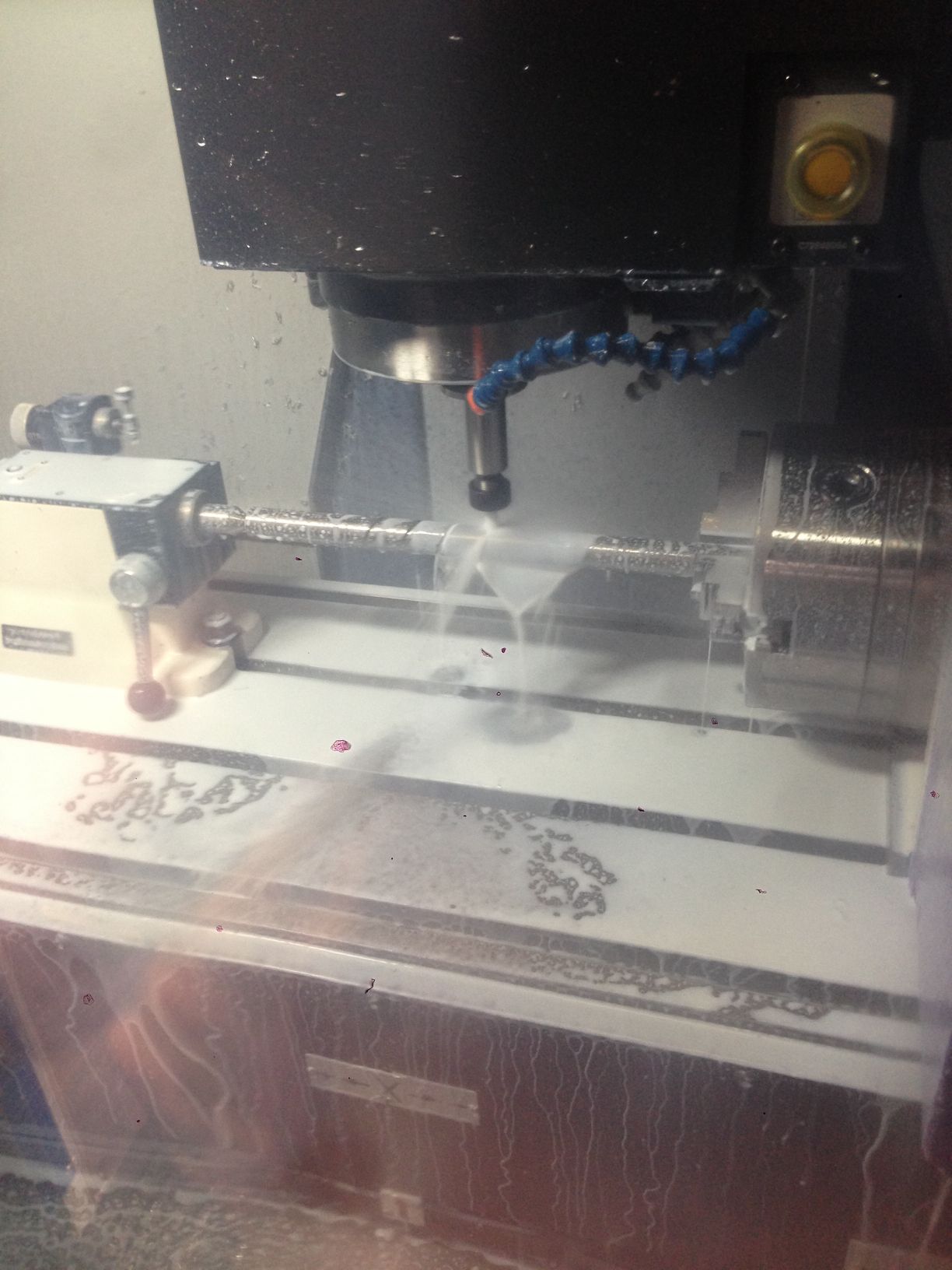
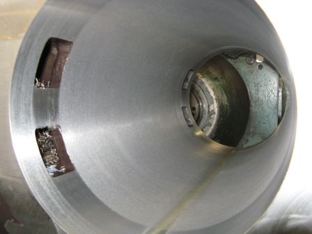
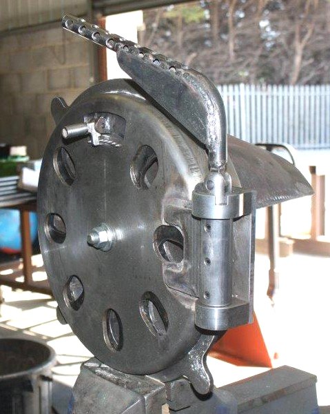
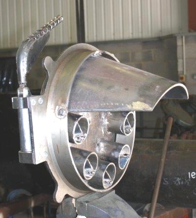
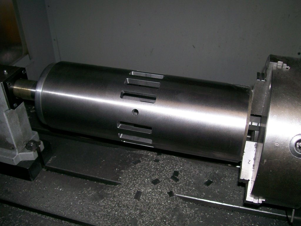
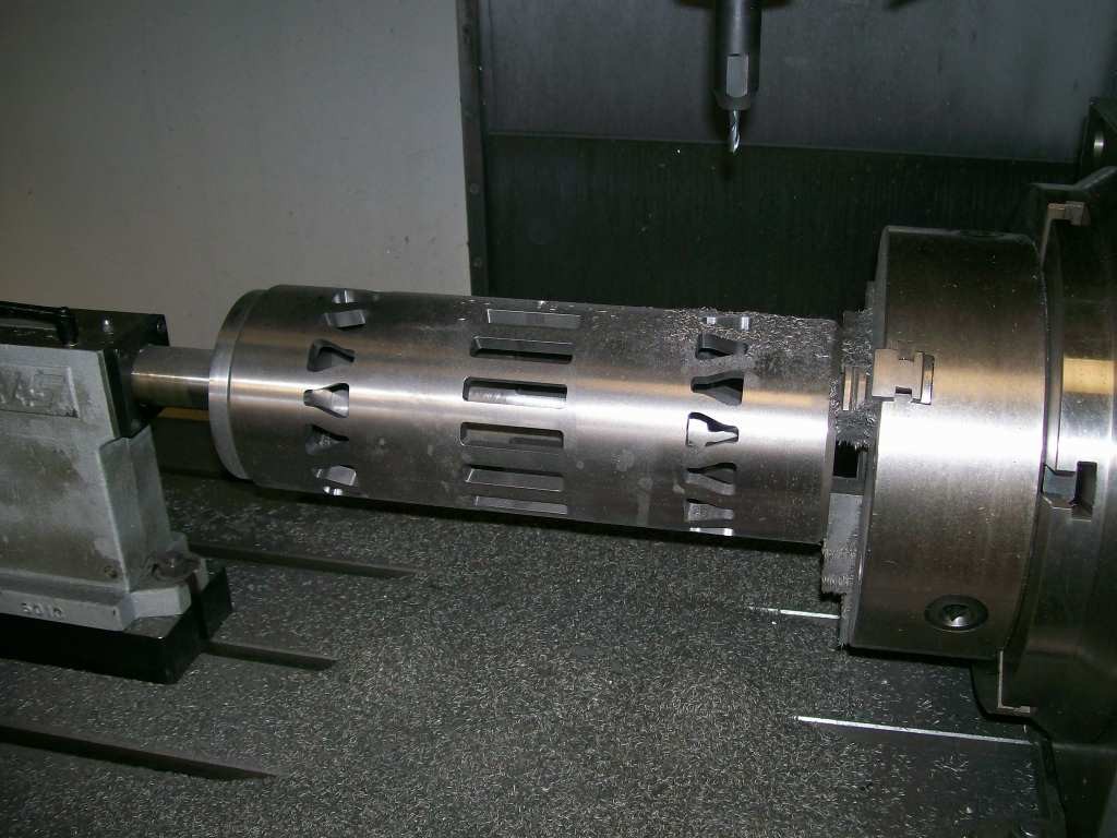
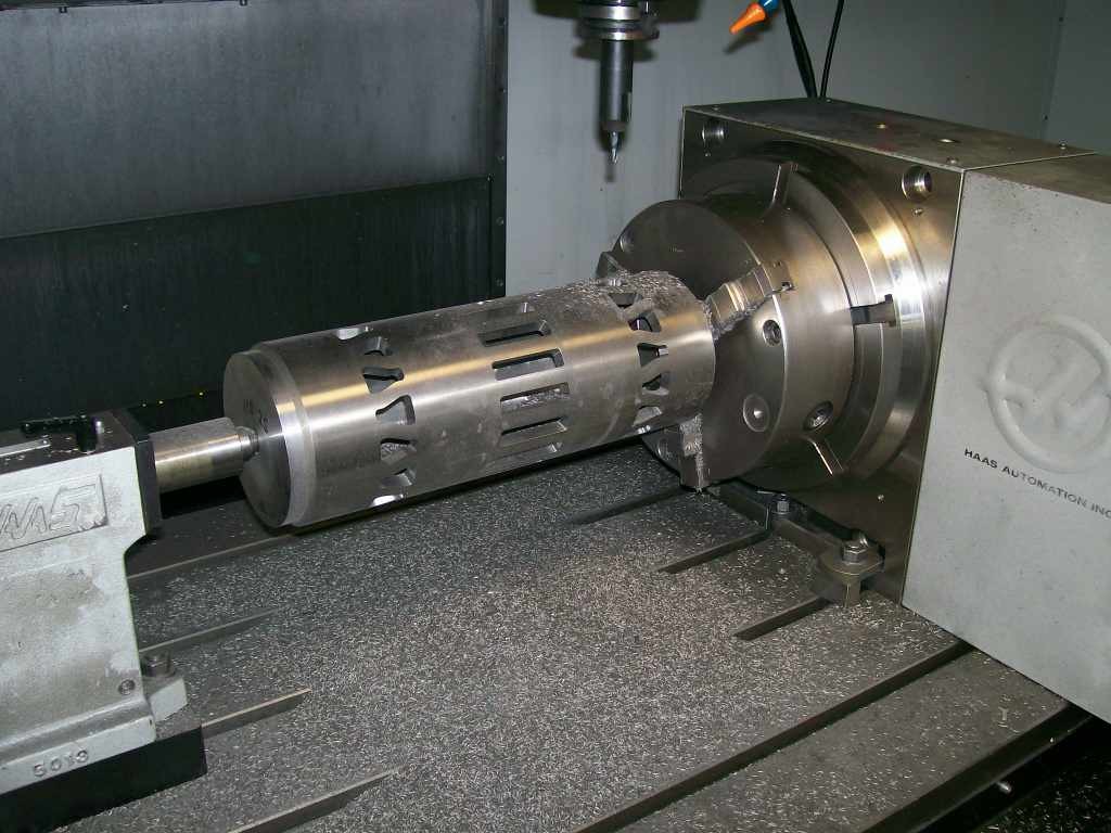
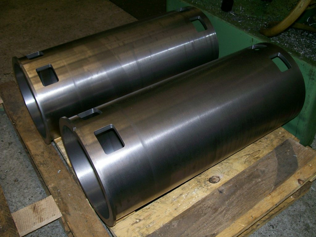
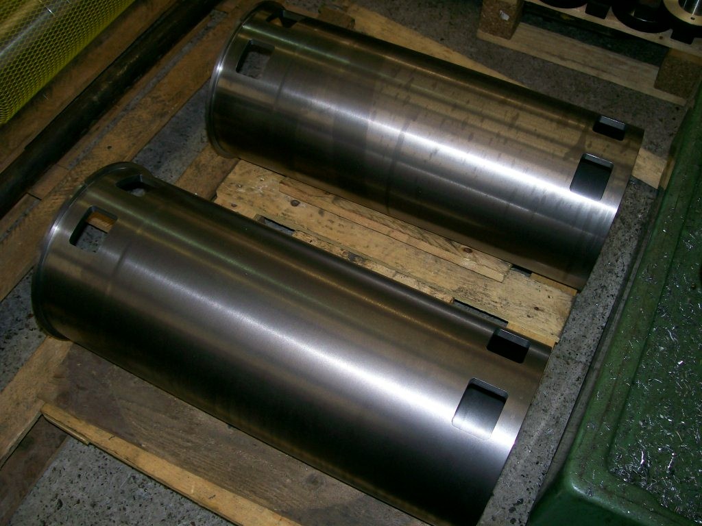
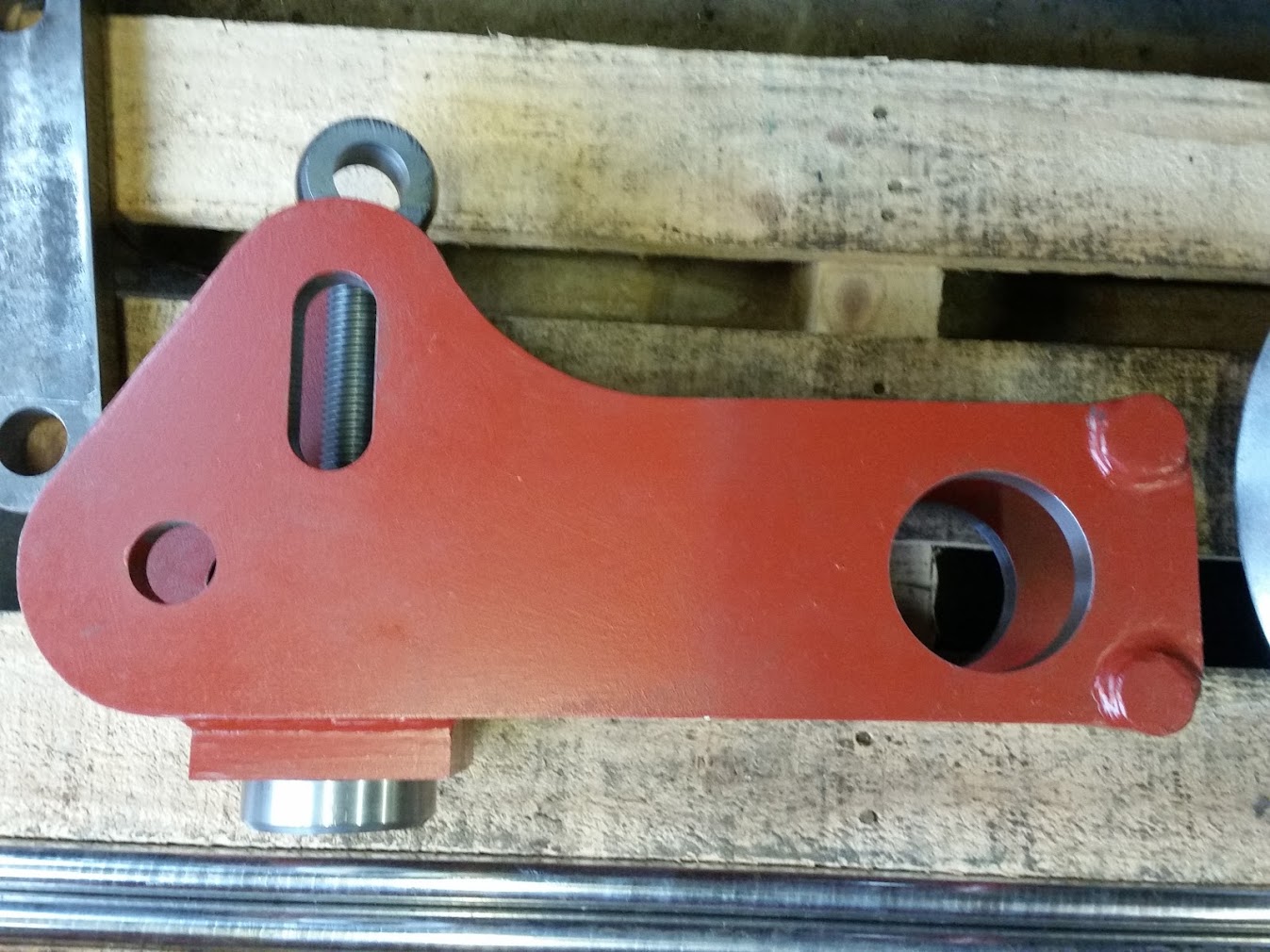
This is the completed indicator shaft. This component was a worry as we had a really high quote from one company but The company making it now is much more sensible.
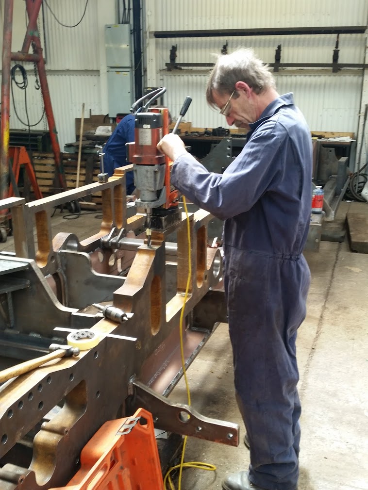
Here is the Indicator shaft spirol being machined. The unit on the left rotates the shaft as the table is traversed under the cutter.
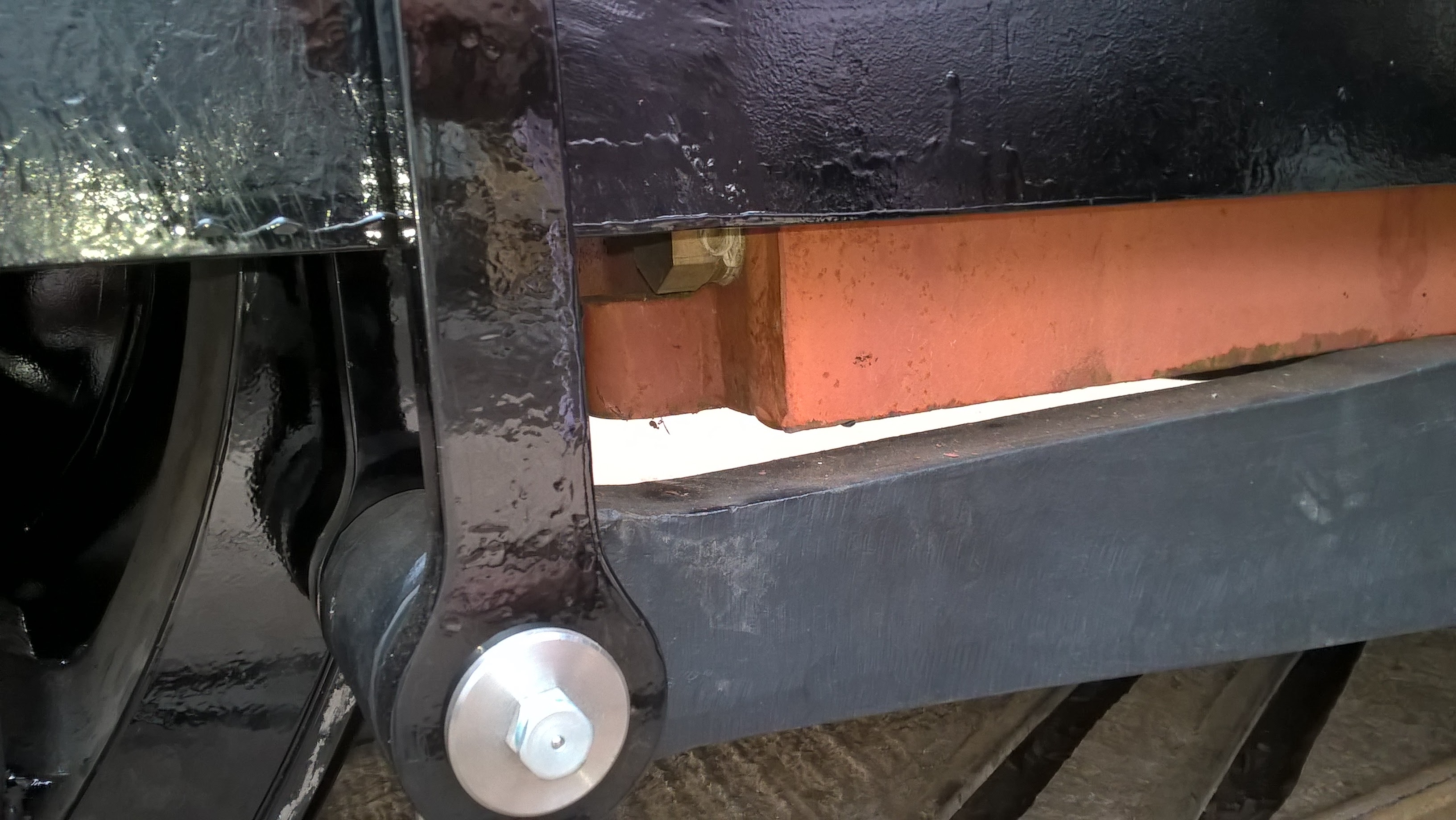
I did a total component count today of the models that make up the main assembly and the number is 6592. I had the main model out a part of a review with Ian to dot some i's and cross some t's We have had the boiler measured accurately so that we can check the clearances around the brake shaft as that is very close to the back of the boiler. The boiler is actually 9mm shorter than the design which is remarkably accurate considering the size and the way welding can shrink things. The extra 9mm will be a real help as it gives us extra space just where space is at a premium.
I have asked the CAD software to give me the position of the centre of gravity and it looks like we will need to add about a ton of weight at the front to optimise the weight on each set of main wheels. A lot of this was caused when the thickness of the boiler material was increased from 10mm to 12.5mm. A lot of the extra material is at the back of the engine.
Modelling progress up to 26th February 2015
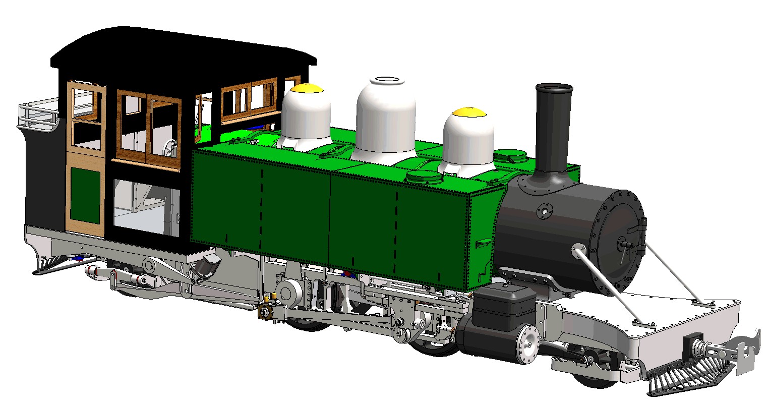
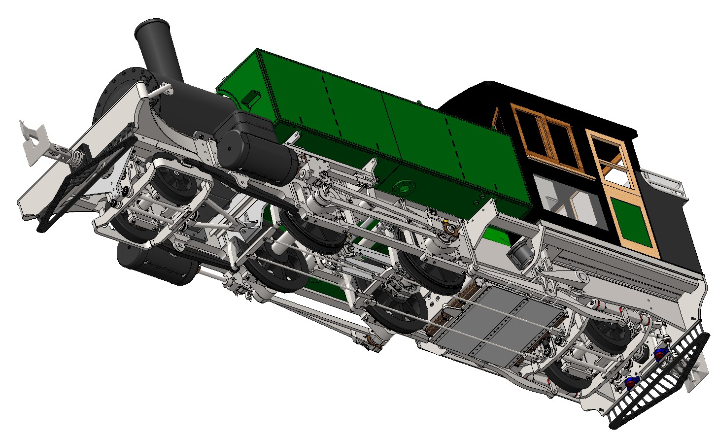
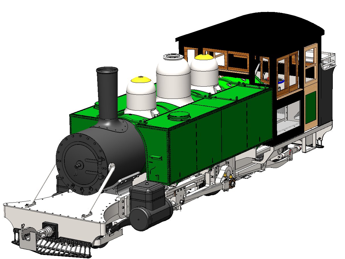
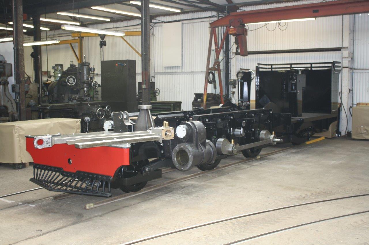
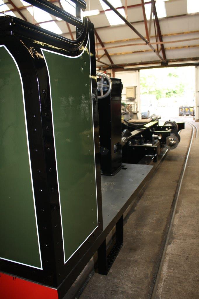
The front apron plate and its parts are now modelled and I can now glimpse the end of the tunnel. Here is a picture of the model so far
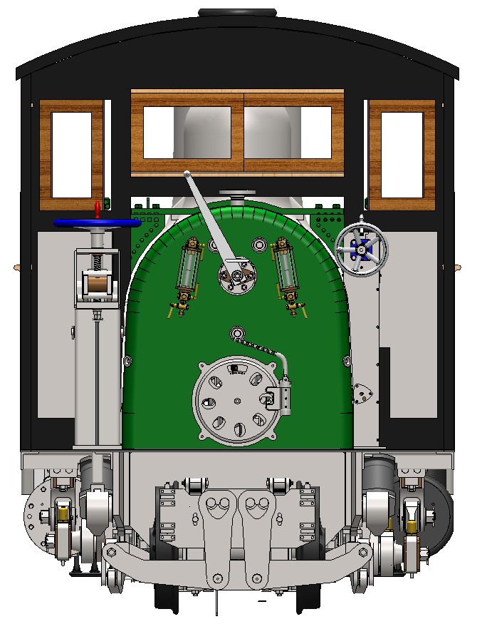
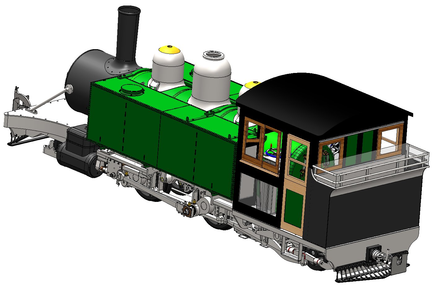
Latest assembly model of LYN.
Latest assembly model of LYN Drivers eye view.
I still have a lot of detail drawings to create (about 200) and I will be doing them over the next month or so. I also need to start a proper assembly model assembled carefully from the parts and subassemblies. The one above has been built from the top down and now we need one built from the bottom up starting with the frame rather than finishing with it! We have a design review next week and, depending on how that goes, I should be able to release the frame drawings for manufacture.
Modelling progress up to 1st March 2015
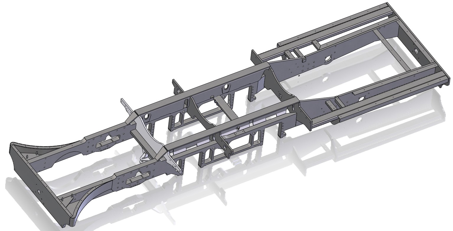
I have spend the weekend preparing for the design review mtg on Monday. The model of LYN is now as up to date as I can get it and there is not much more to add. The model is now free from constraint errors - hard to achieve and even harder to maintain. The completed frame is now looking much more complicated with all its footplate mountings. I still have a couple of more brackets to fit and the watertank balancing pipe to fit to the frame but the bulk of the engine is now complete. I have added a link to the latest weight and centre of gravity information. This is output from the main model and I have found it to be amazingly accurate. Ian is using this information to optimise the suspension. The datums for the model are Z = horizontal along the length of the engine and Z0 is at the front end of the boiler shell, Y = vertical and Y0 is on the centreline of the boiler tube, X = horizontal across the width of the engine and X0 is on the centre of the boiler
Latest assembly model of LYN Viewed from Underside.
Latest frame model.
Modelling progress up to 12th March 2015
The frame drawings are complete and have been issued for checking and quotation. We have a meeting on Monday 16th March with a possible manufacturer. I have made the assembly drawing pdf file for the frame available below
I have also had to get involved with the coupling provision for LYN. My understanding was that the couplings would be purchased complete but it now appears that some of the supplied components will need further work to make them usable and extra components will need to be sourced. I have put a link to the assembly drawings for the 2 couplings below:-
The detail drawings of the front pony truck are mostly completed and this means that the rear pony truck is also well on as it shares a lot of components.
The Frame meeting went well and it would be worth keeping an eye on the 762 Club Homepage for an announcement soon. Ian has nearly finished the stress calculations for the frame, a very complex task, It is necessary to calculate the stresses on the frame for a number of load situations and we have some small mods to do at the rear to cope with the loads that lifting the engine by its buffer beams would create (this might happen is the loco was derailed and lifted back onto the track without understanding the limitations of the Baldwin frame design).
The machining of the cylinders is progressing and I am hoping to have some pictures soon.
Here is a picture of the coupling and connecting rods after machining.
Progress up to 20th March 2015
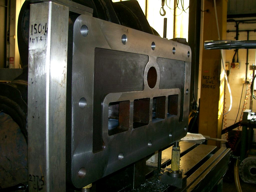
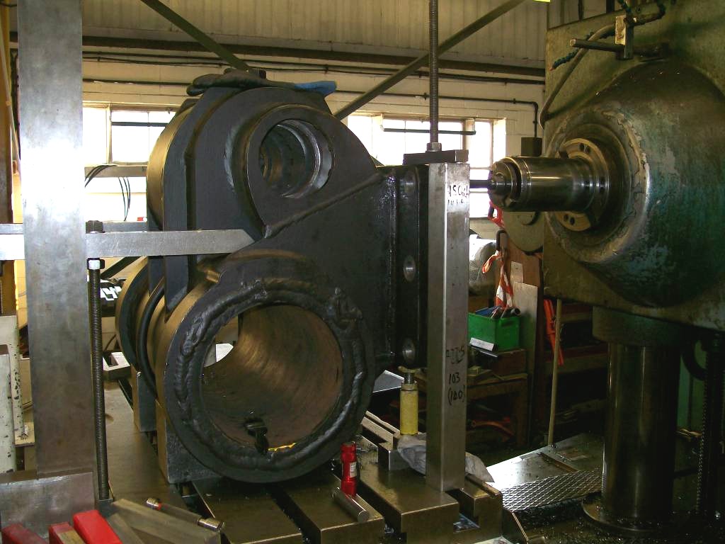
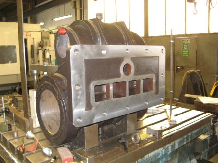
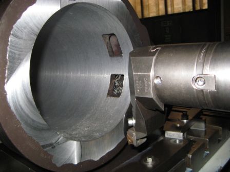
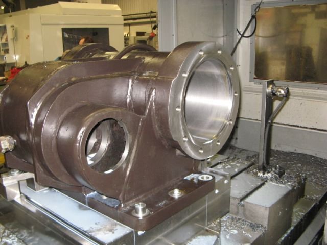
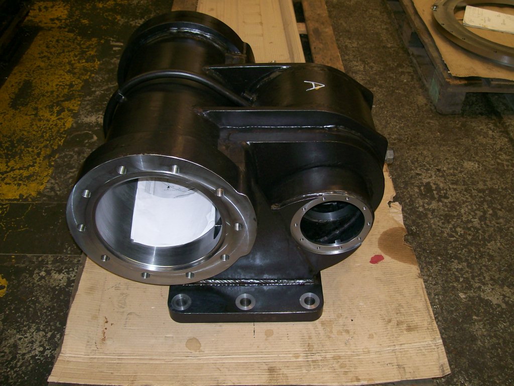
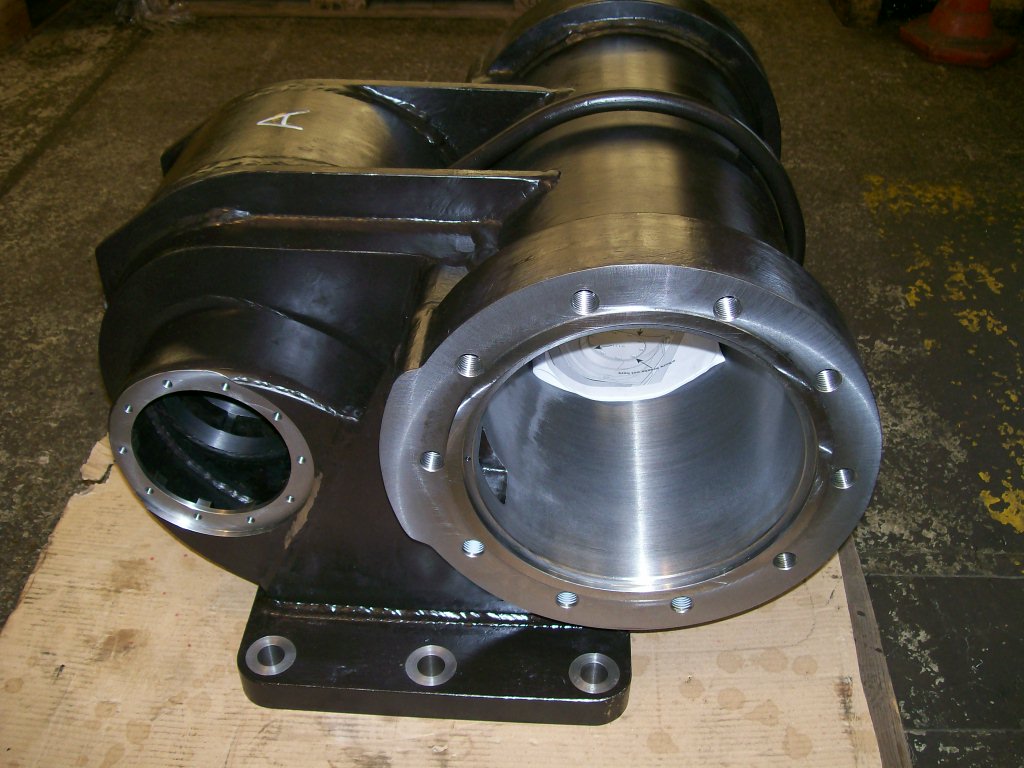
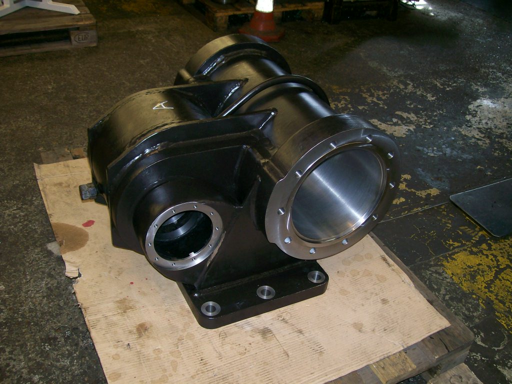
Robert Frost has sent me the first pictures of the cylinder machining. His comments below:- We now at last have first cylinder on the borer.
Cylinder has been set up and various features equalised as far as possible and then the frame flange skimmed up and mounting holes drilled – unfortunately there was insufficient material to clean up the face so we will need a shim (3mm) in between. We have been able to spotface the rear of each hole except the two tapped holes where there is insufficient space to set up the backfacing tool.
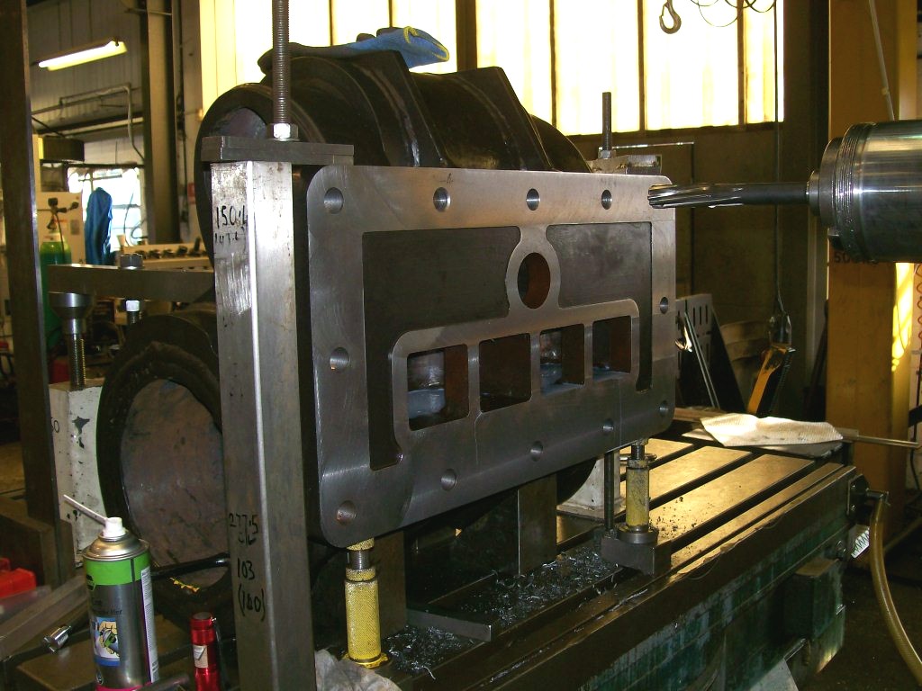
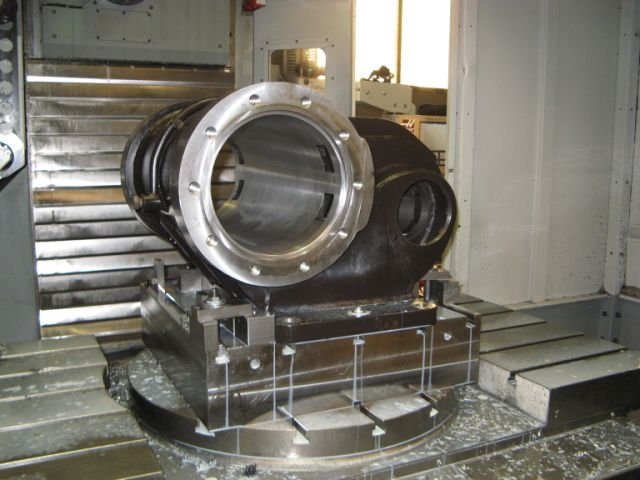
Plan is to repeat frame flange machining on the other cylinder, then to lay the cylinders down on this face on the table and set up to machine the bores through.
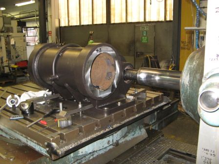
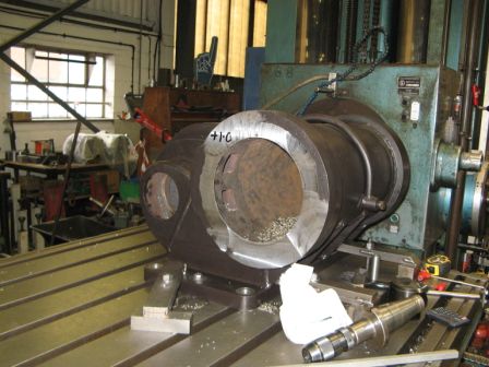
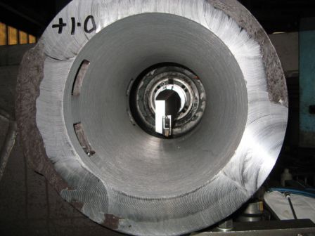
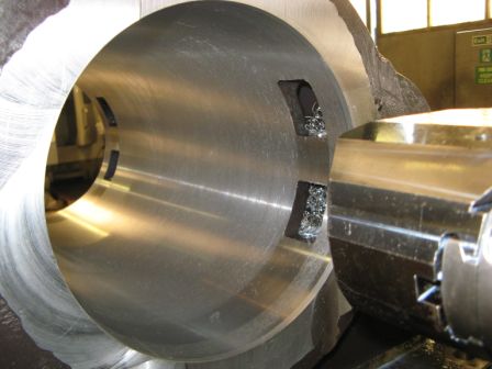
More pictures of the cylinder machining from Robert Frost.
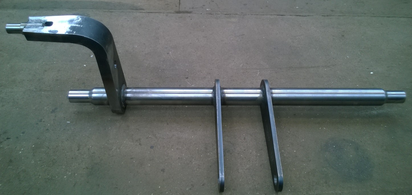
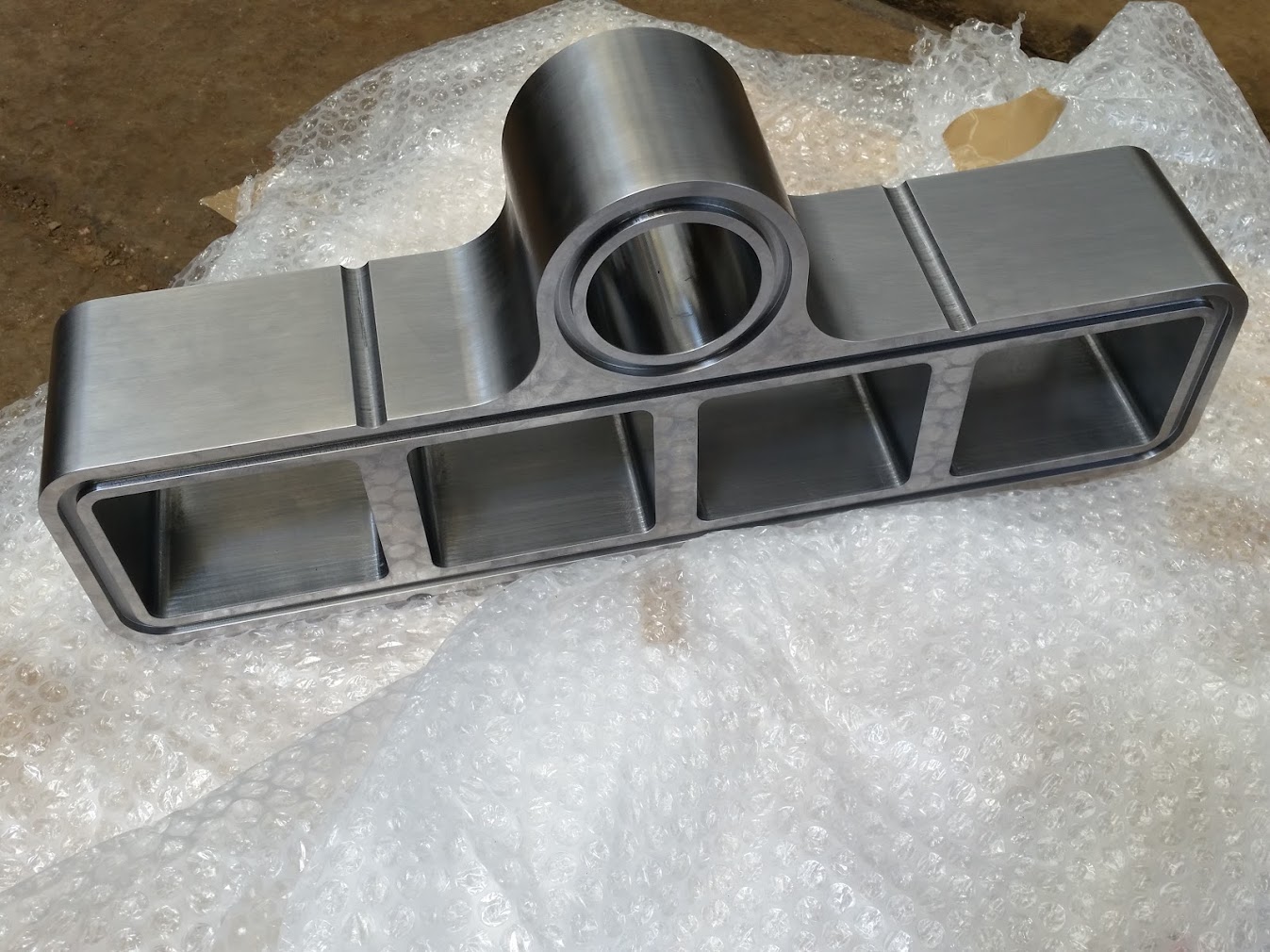
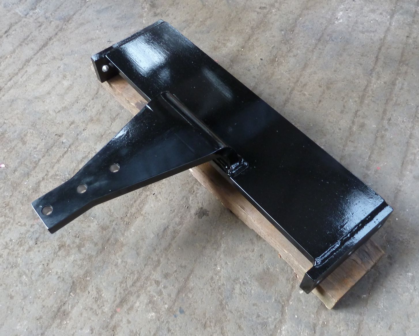
This is the finished weigh shaft made by Alan Keefs Ltd
Progress up to 23rd April 2015
No new pictures yet.
The cylinder main units are now nearly machined and will be ready for the liners to be shrunk in soon. I am hoping to be there so I will have pictures of the process.
All of the drawings have been issued for the manufacture of the frame and work has started cutting out the parts.
I have finished the detailing of the pony trucks and Ian has checked them. I just have to go through the drawings to make sure that any thing that Ian has found that need updating is done and then the drawings will be issued to Keef's for manufacture. The pony truck axle assemblies have already been checked and issued to them.
I have a meeting tomorrow with Ian to go through the ashpan which is the last of the major assemblies needing the design checking and detailing for manufacture. I have already detailed the current design but there are significant opportunities to simplify the design and increase the robustness of it. Most of the detail drawing already done will just update automatically but a few will need significant redrawing.
The firehole door is close to completion and I am trying to get some pictures.
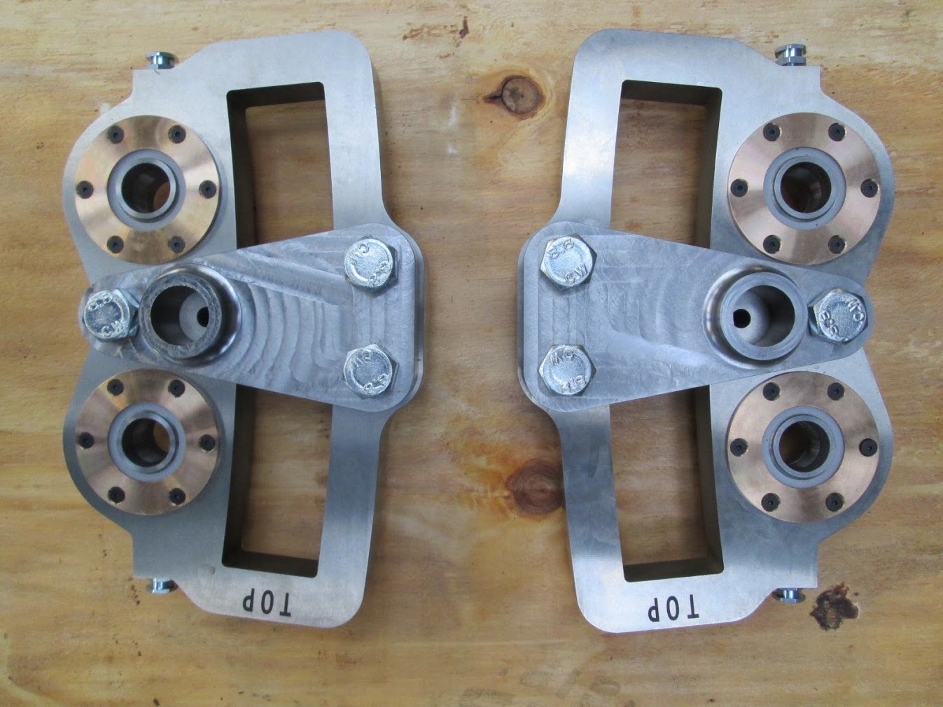
Leading pony truck model.
Trailing pony truck.
Progress up to 27th April 2015
Today Ian and I had a good session sorting out the ashpan. I now have enough information to finish off the drawings. Pictures soon.
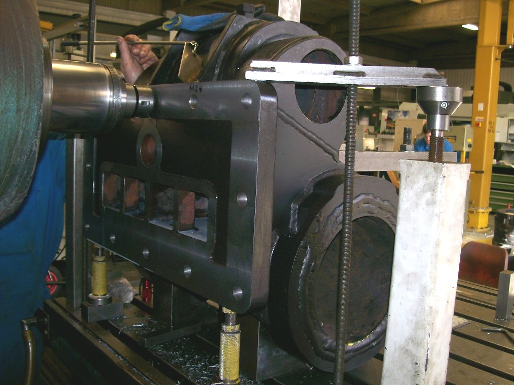
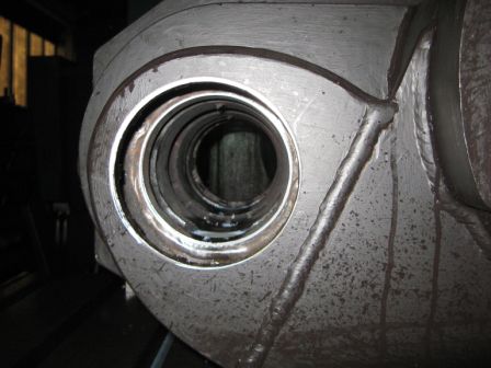
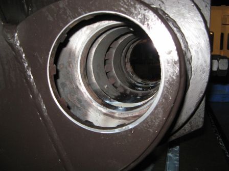
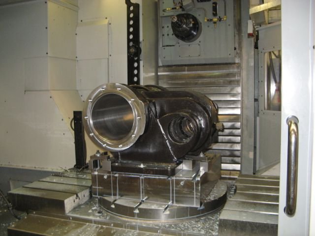
Robert Frost has sent me some more pictures of the cylinder machining and it is looking good.
Progress up to 30th April 2015
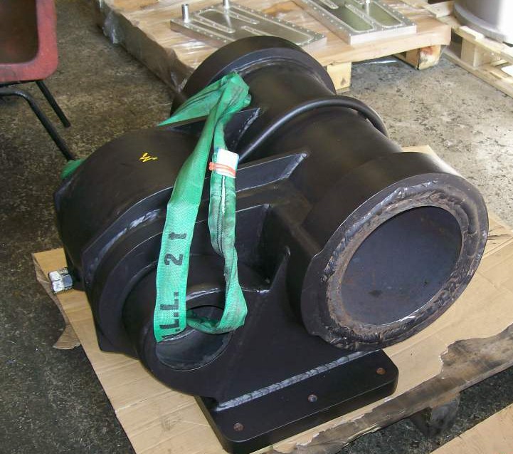
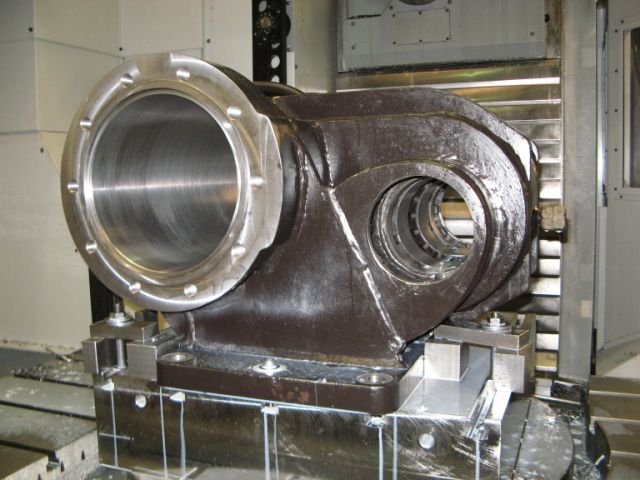
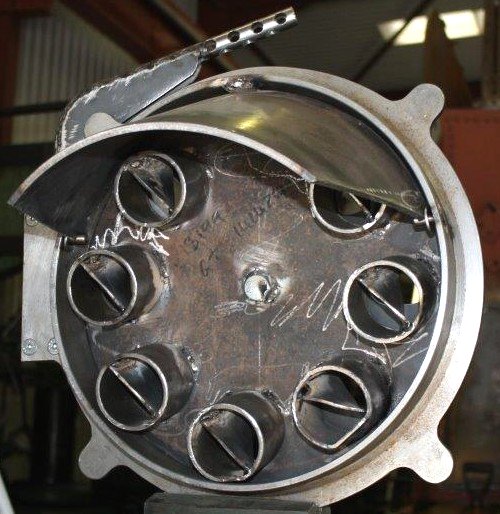
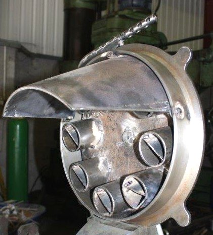
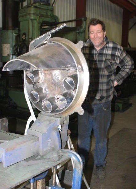
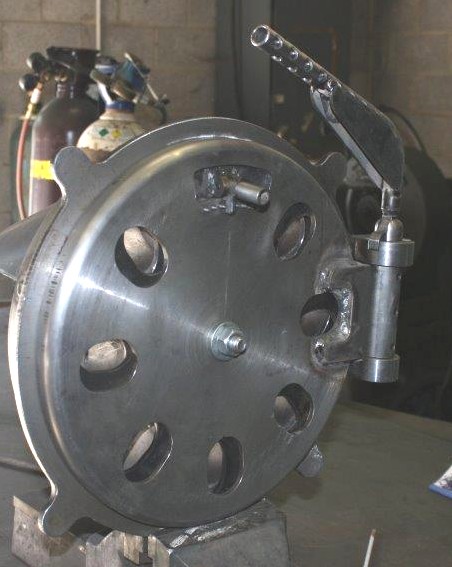
Just received these pictures of the firehole door made by Andy Bennett. Also a picture from Robert Frost of the 2 fully machined cylinders awaiting liners
The liners are now nearly finished and we will soon be shrinking them in.
Progress up to 4th May 2015
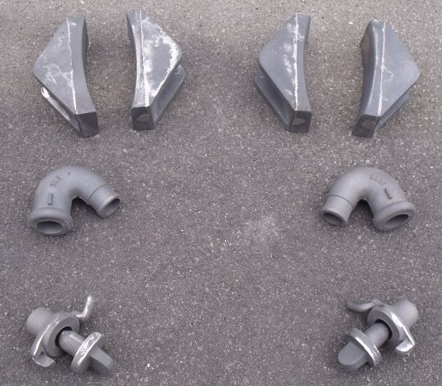
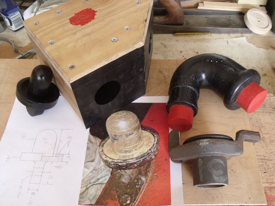
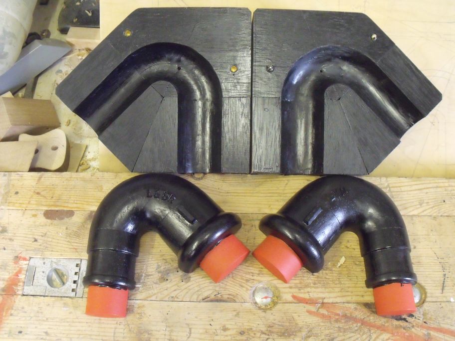
I have just received these pictures of the brake pipe swan neck and the other components that blank it off when it is not connected. I have also included a couple of pictures sent to me by Brian Lloyd of the patterns he has made for some of these components.
Progress up to 24th May 2015
The drawings for the front pony truck are finished, checked and issued to Keef's for manufacture. The rear pony truck drawings are finished and just awaiting checking. The rear pony truck has a lot of components in common with the front pony truck so there will not be so many drawings to update.
I am still working on updating the ashpan ready for doing the drawings. should be ready to detail next week.
The total number of parts in the full engine assembly model has now reached 6675. It is no wonder that it can take 15 mins to open. The total predicted dry weight of the engine from the full assembly mass properties is 19395.40 Kilo which is about 19 tons this weight includes about 700 Kilo of coal.
Progress up to 3rd June 2015
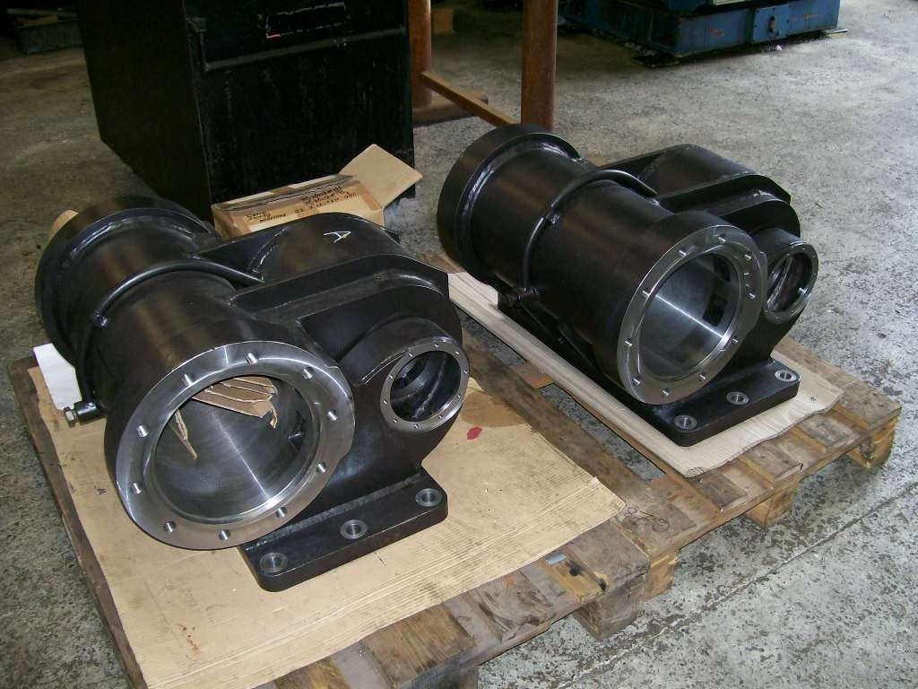
Just received these pictures from Robert Frost of the 2 fully machined cylinders awaiting liners and the nearly finished liners ready to be fitted
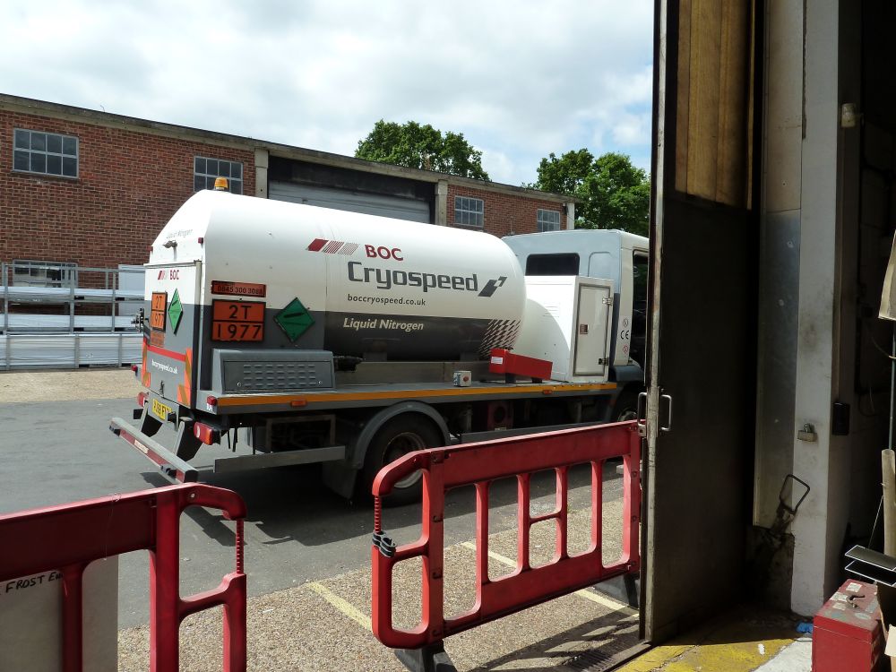
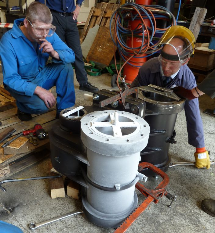
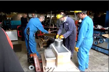
Shrinking in the liners 18th June 2015
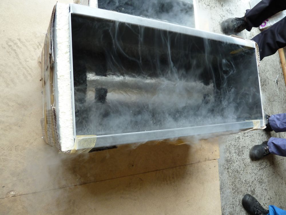
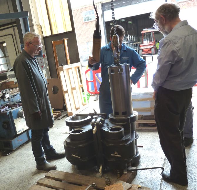
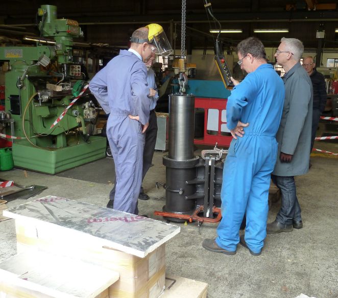
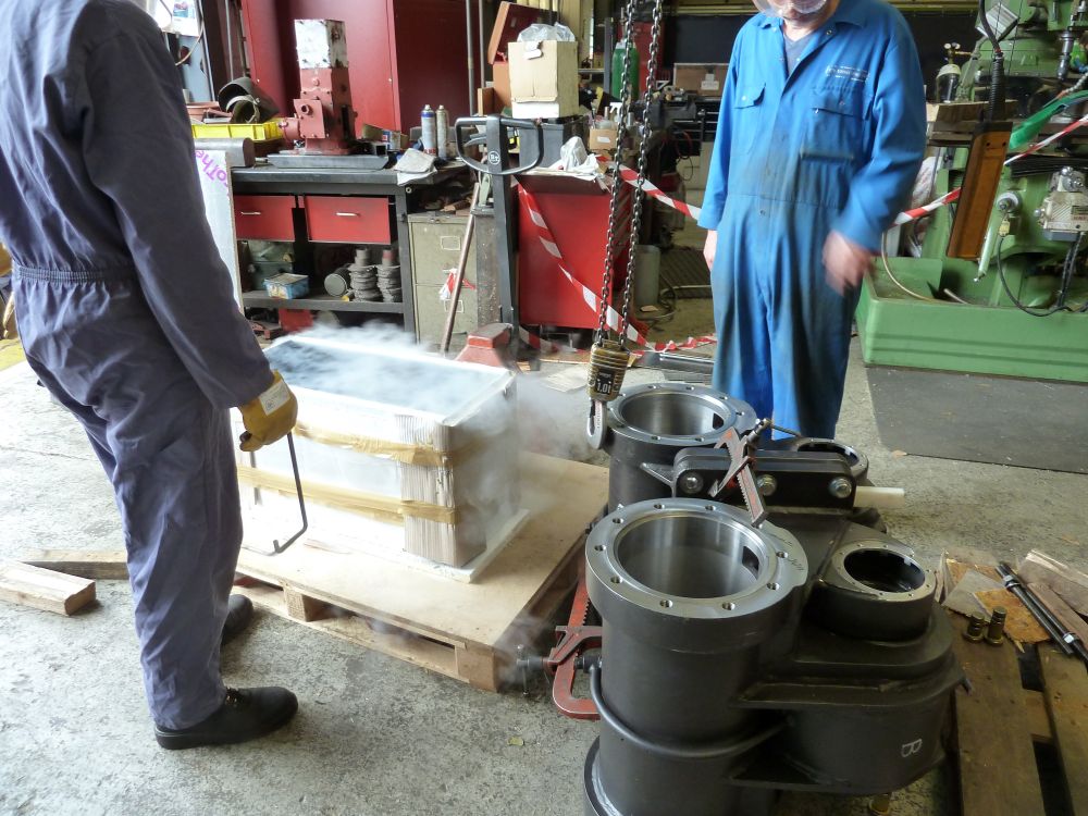
The Design team (Ian, John & Mike) visited Frosts to see the liners fitted to the cylinders. This was a very tricky operation and the myth that there is plenty of time is really not true. You have less than 35 seconds to get the cold part into the warm part and correctly position it before it is permanently held. I took a few pictures and a video of the process.
The liquid nitrogen being delivered
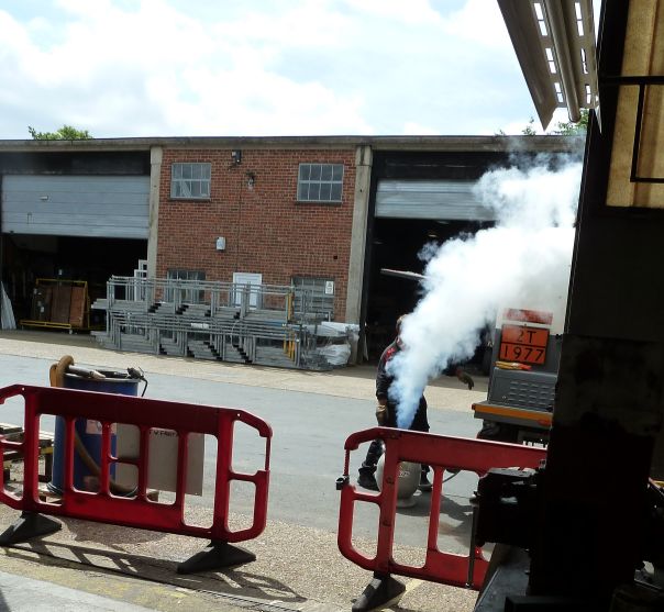
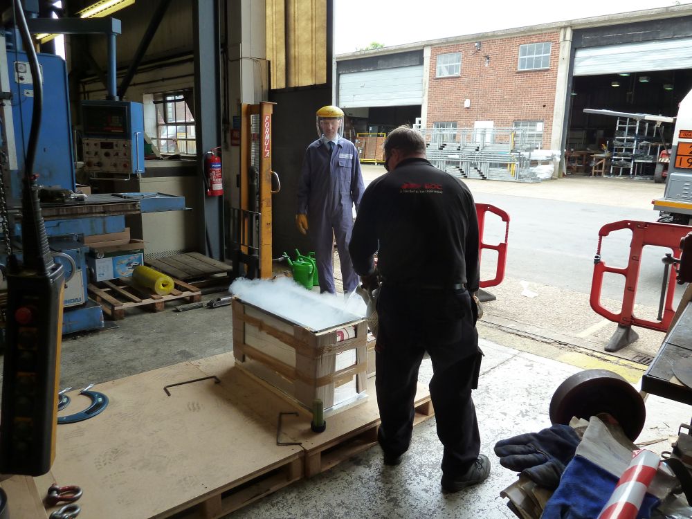
Filling the insulated container
Filling the cooling bath
The cylinder liner in the bath
Checking the alignment of the hoist
and check again
Ready to lift the cylinder out of the bath
One cylinder finished & checking the alignment of the second.
Click the picture to watch the video
Progress up to 26th June 2015
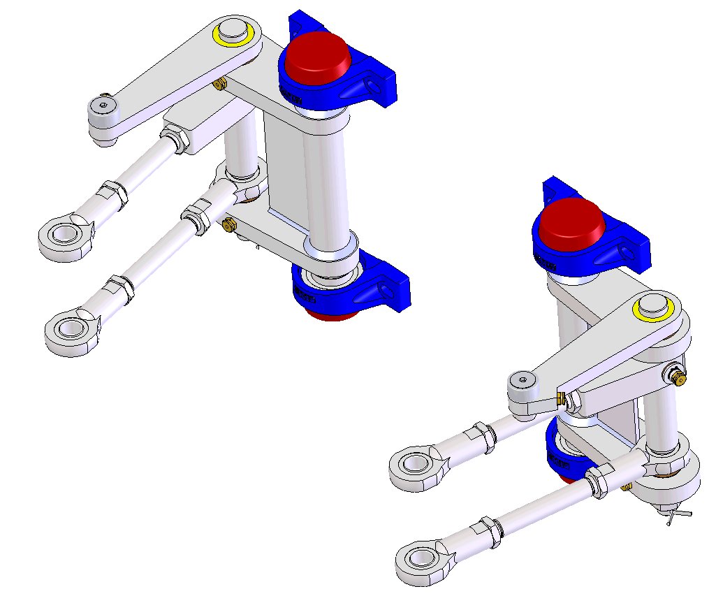
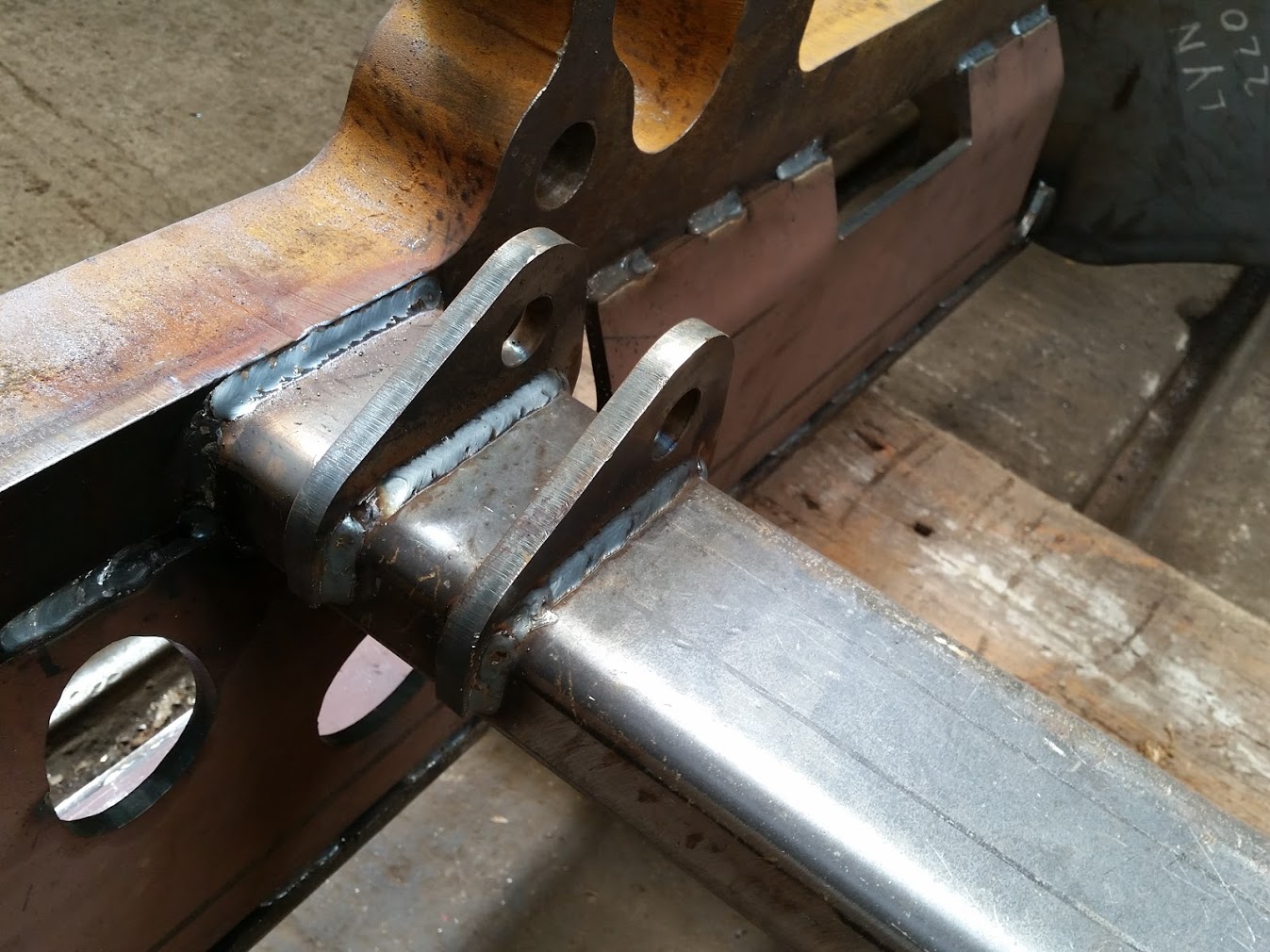
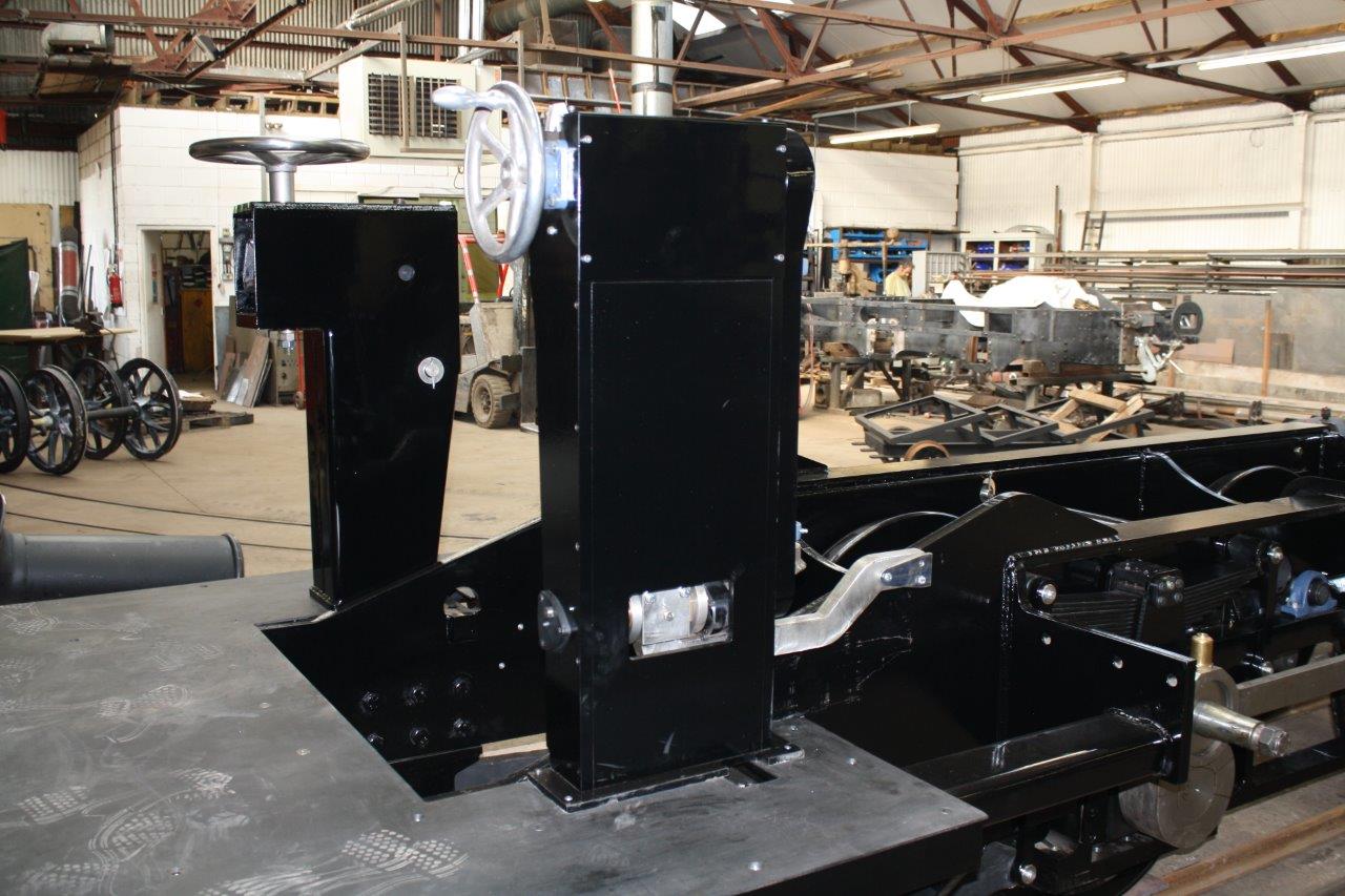
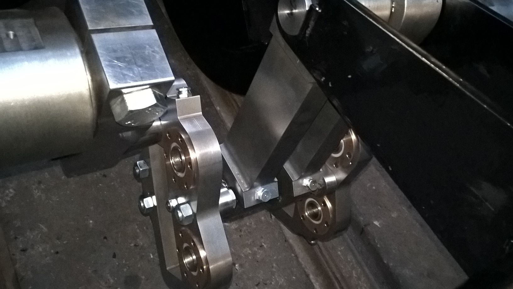
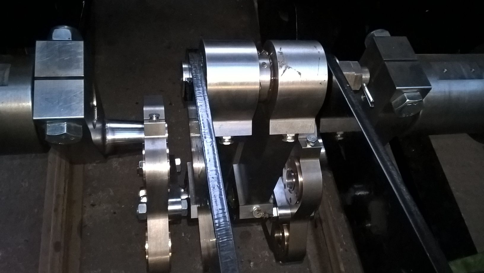
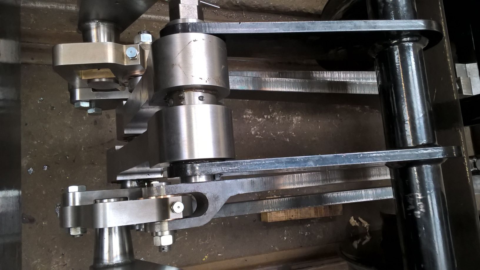
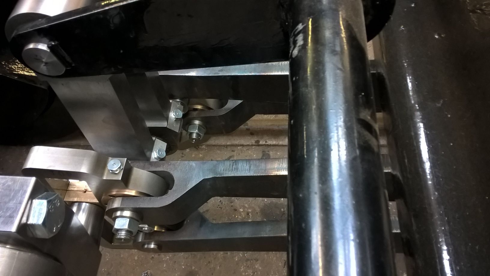
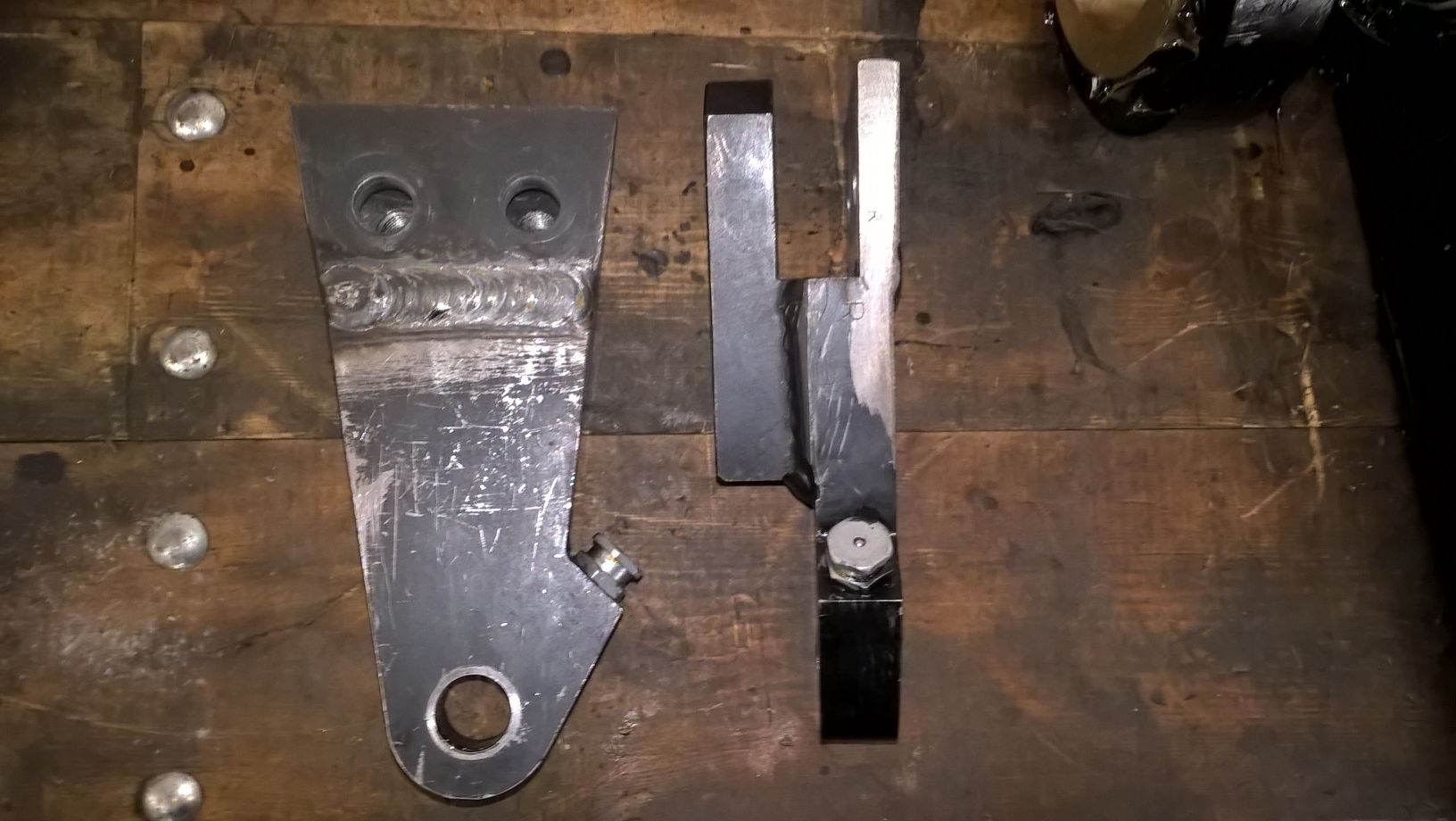
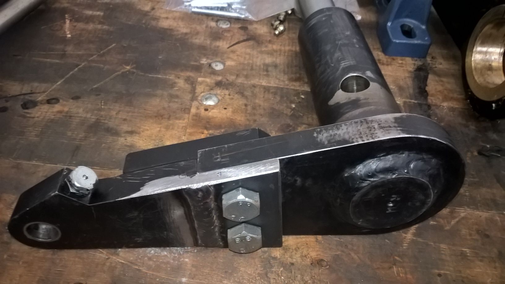
I have finished the drawings for the brake stand and these are issued for checking. I have also fnished and issued for checking the rear pony truck control assembly. This is mounted on the rear buffer beam and replaces the yoke that would normally be used as the deeper firebox is in the way. The lever mechanism allows the truck to move sidways in a controlled manor. Because of the space limitations underneath the footplate the mechanism also controls the fore and aft movement of the truck.
The parts for the frame have been cut and delivered to Alan Keefs and a company has been identified to assemble them.
Looking up from underneath. Rear truck control assy fitted.
Rear truck control mechanism.
Frame assembly model.
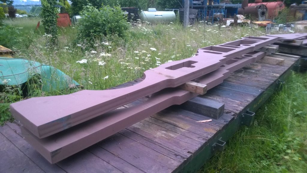
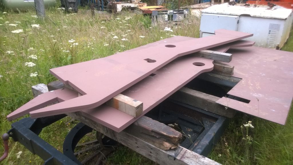
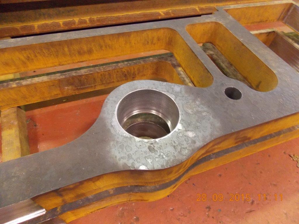
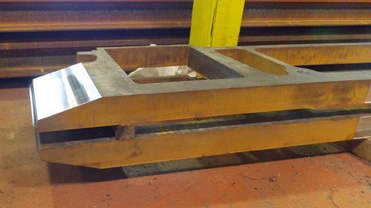
This is the main frame part that we have had to replace so the quality was very poor.
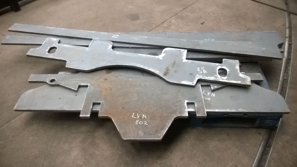
Frame parts at Alan Keefs ready for assembly
Progress up to 4th October 2015
Well not a lot of news since July. We have had to remake the major part of the "free" frames as the cutting was so poor that they had to be scrapped. We have now had replacements cut and these are much more acceptable. The difference is that the new ones were waterjet cut and the old ones plasma cut (and badly at that). The new frame parts are now with the company that is putting the frame together.
I have been working on the design of the ashpan and am well on with the drawings. I have also been completing the parts that need to be bolted onto the frame ready for its completion - Horn guides & brake mountings etc. Some of these will be ready for Ian to check when he is back from holiday.
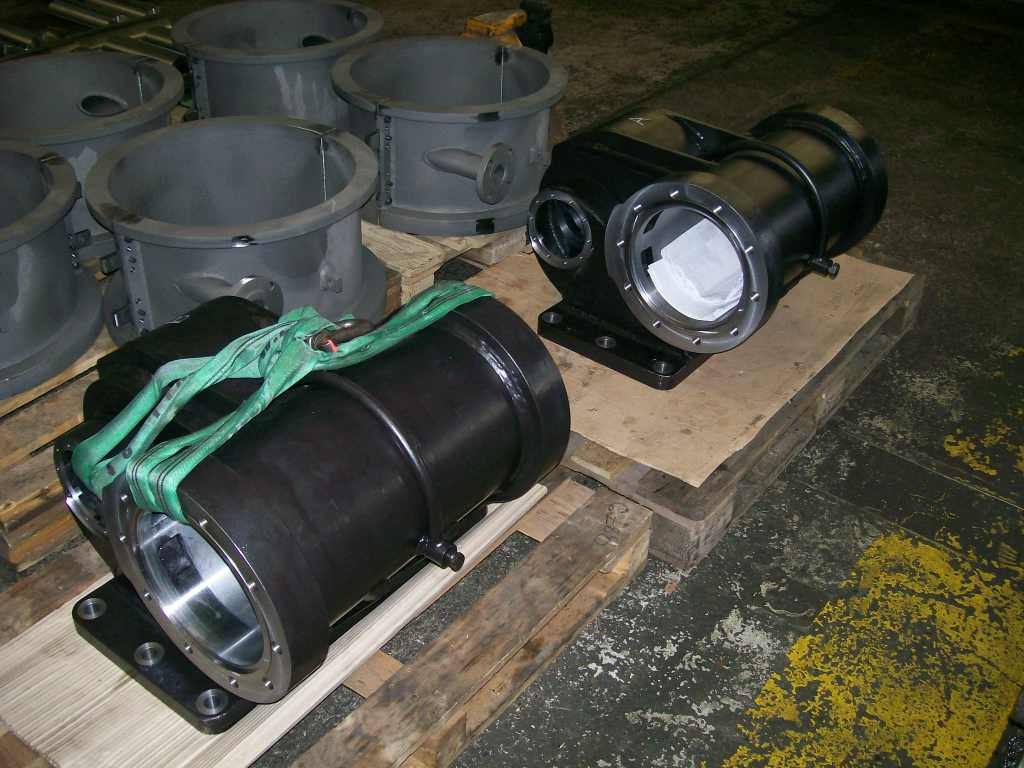
We are into that area where we are finding and solving problems with the build. The SKF bearing blocks for the reverser don't fit the provided mounting holes and it looks as though the supplied items are not to the right design (the bearing blocks, not the provided holes) and may not be original SKF items. Another problem is sourcing the SKF spherical roller bearings for the big and little end of the connecting rod. We have tried for some while to source these with no success and it now appears that, although they are listed on the SKF website they may never have been produced! Ian is looking to see what can be used in their place.
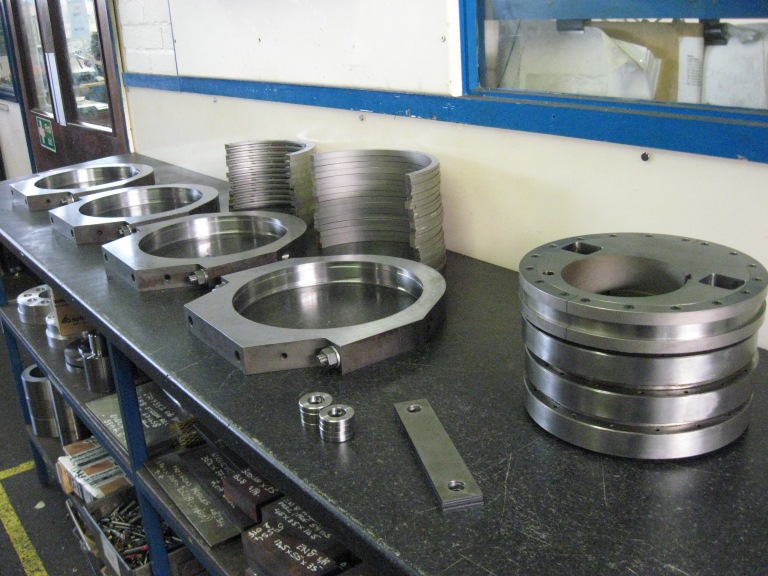
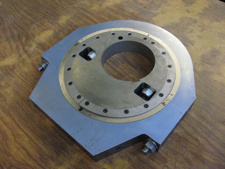
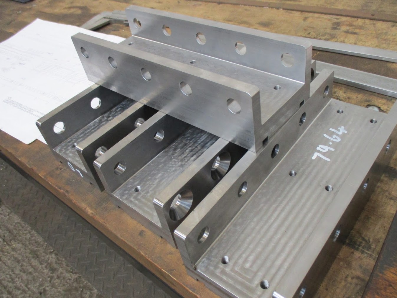
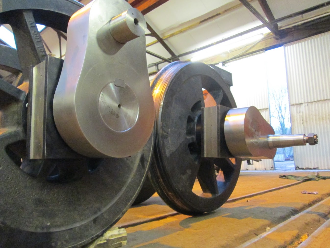
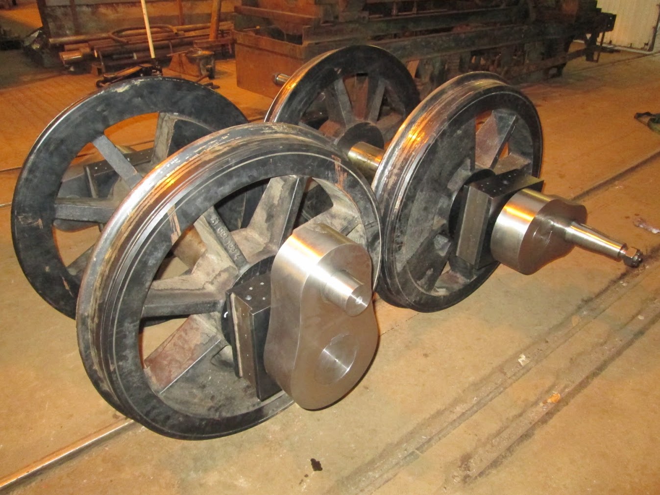
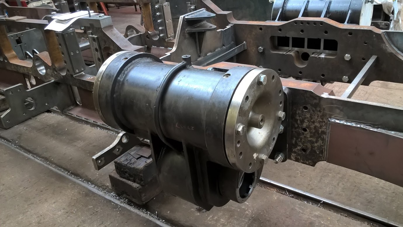
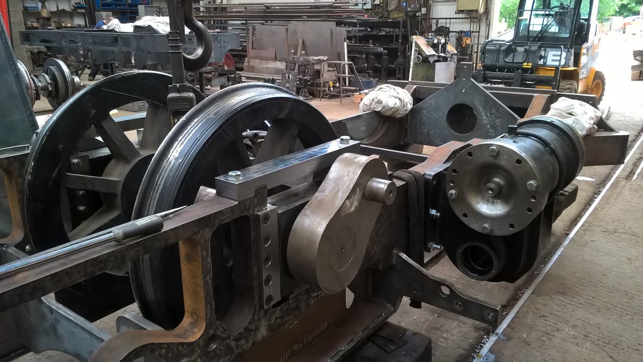
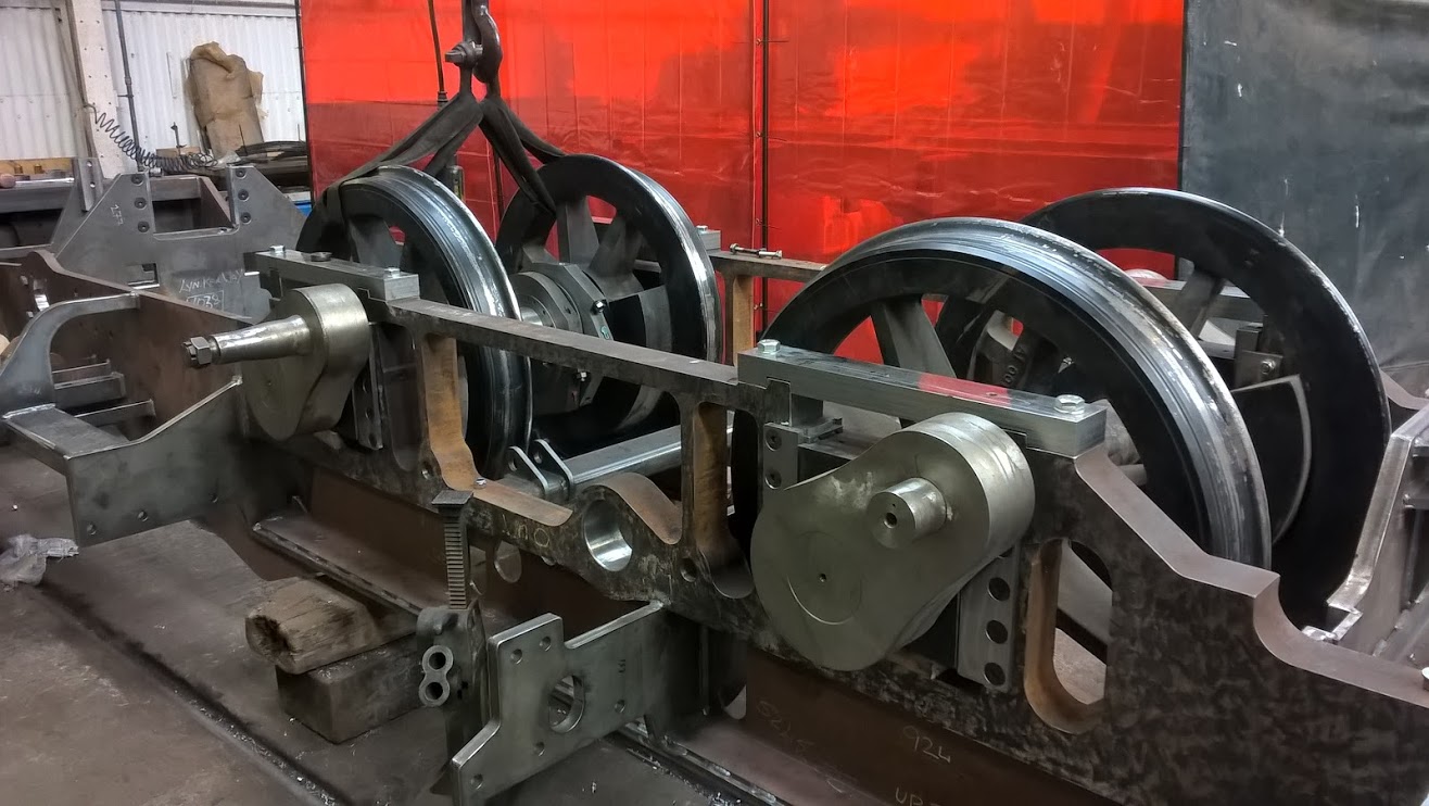
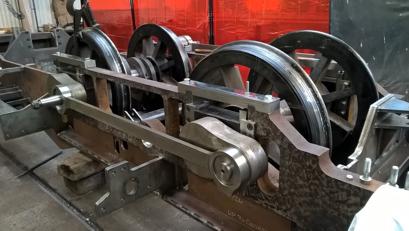
All the eccentric components ready for assembly onto the engine.
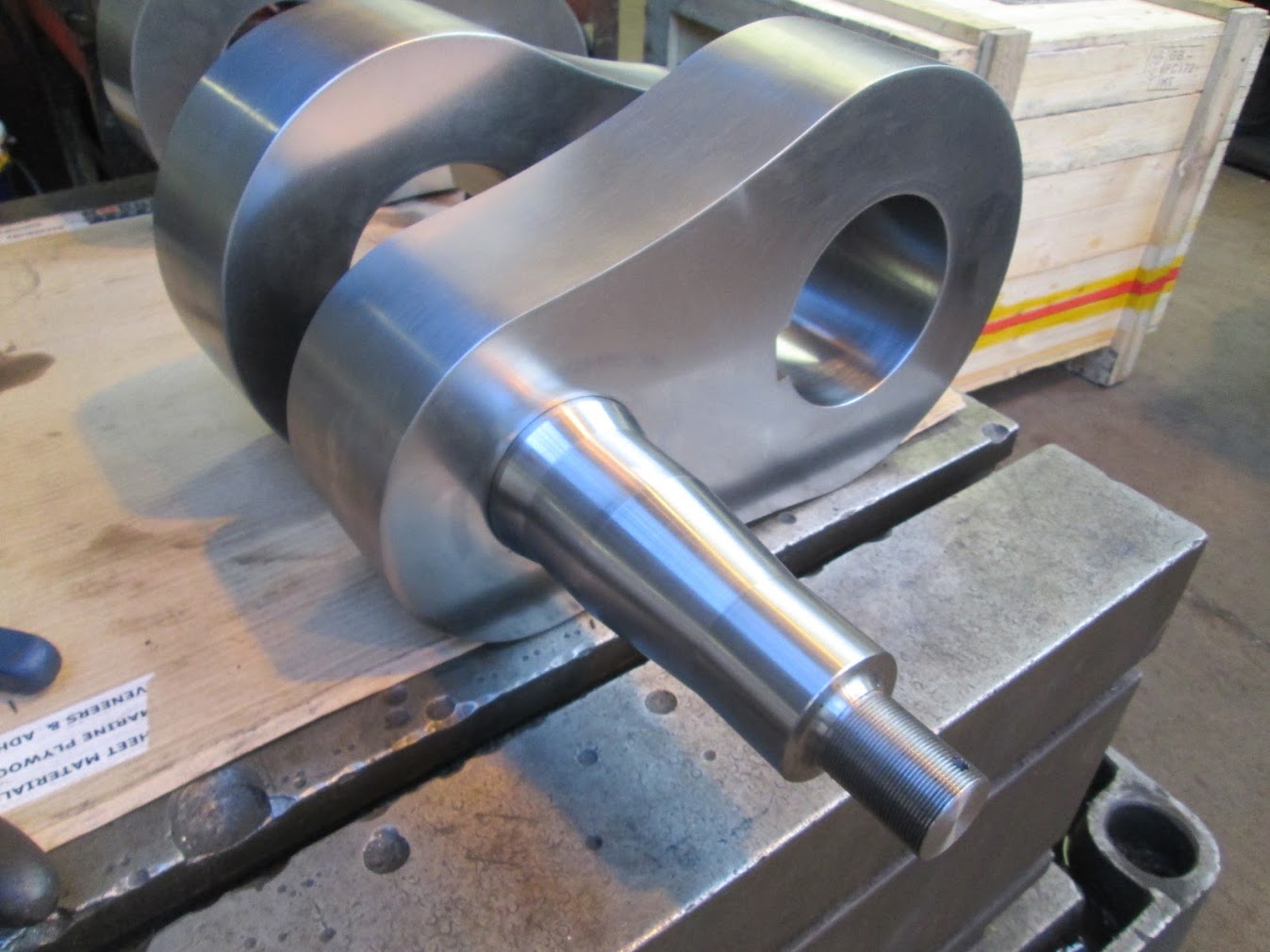
Assembled eccentric.
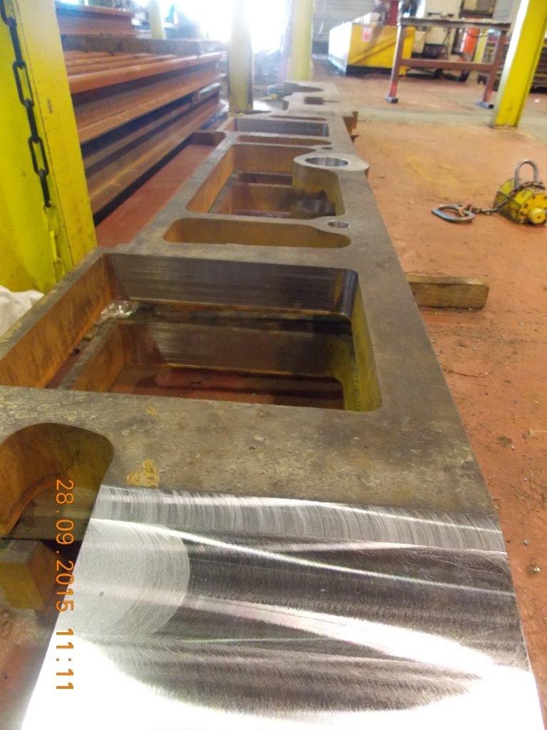
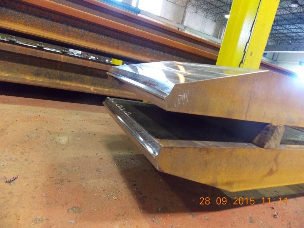
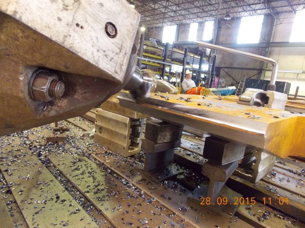
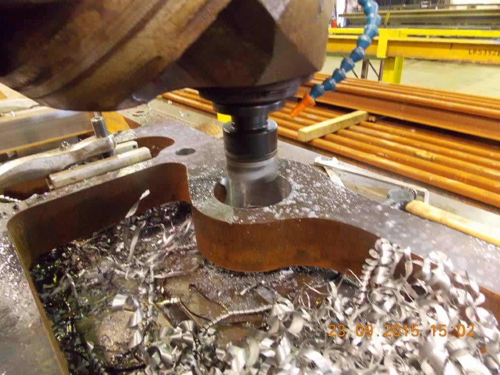
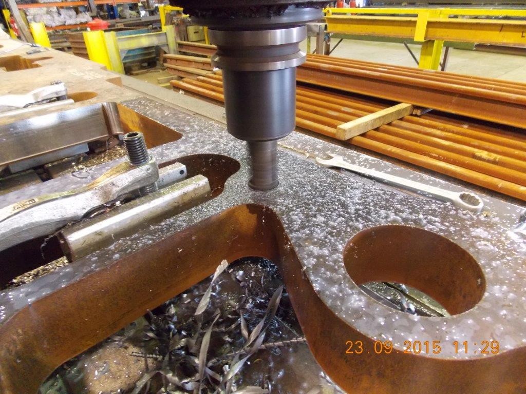
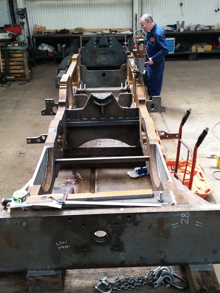
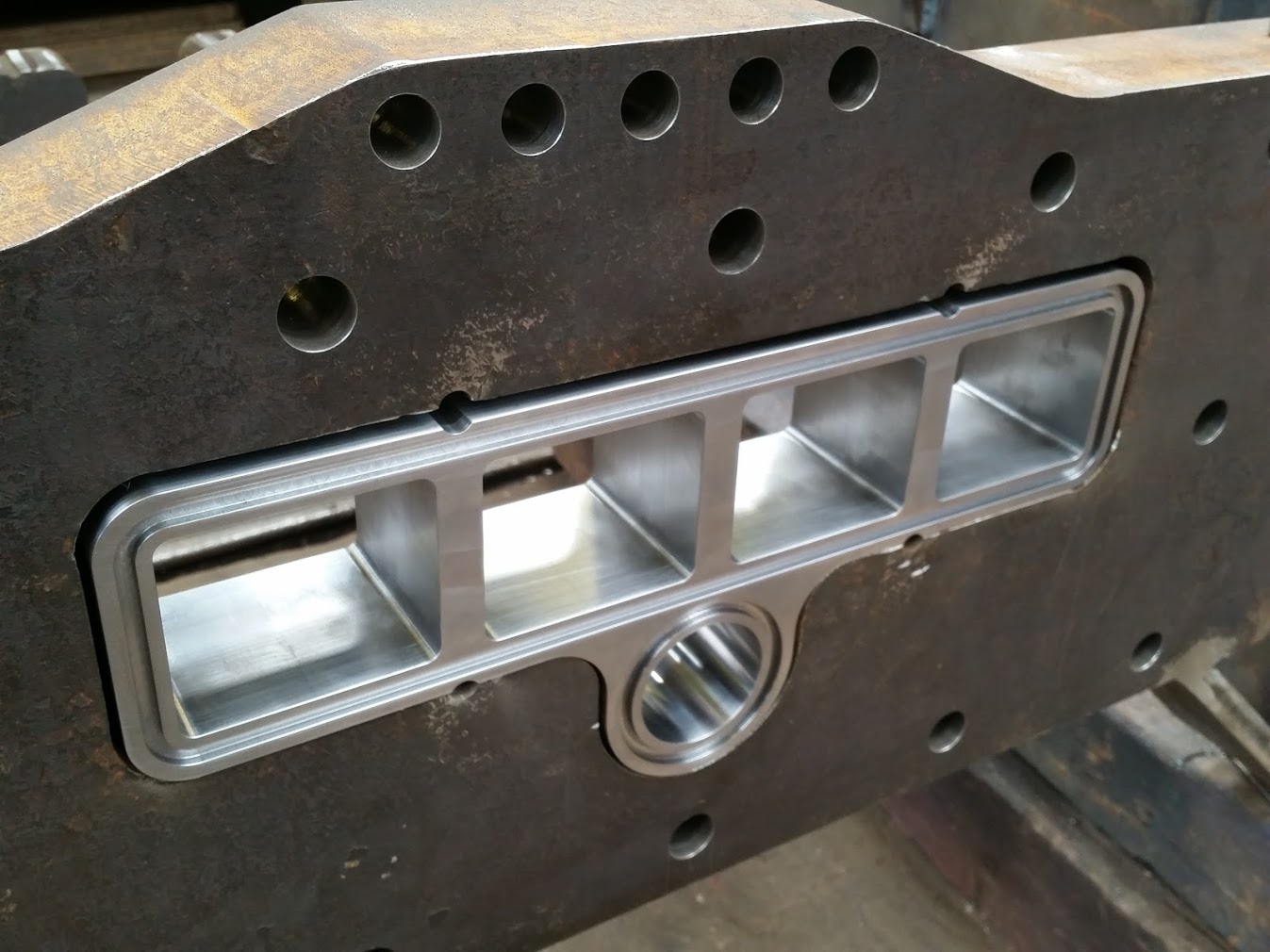
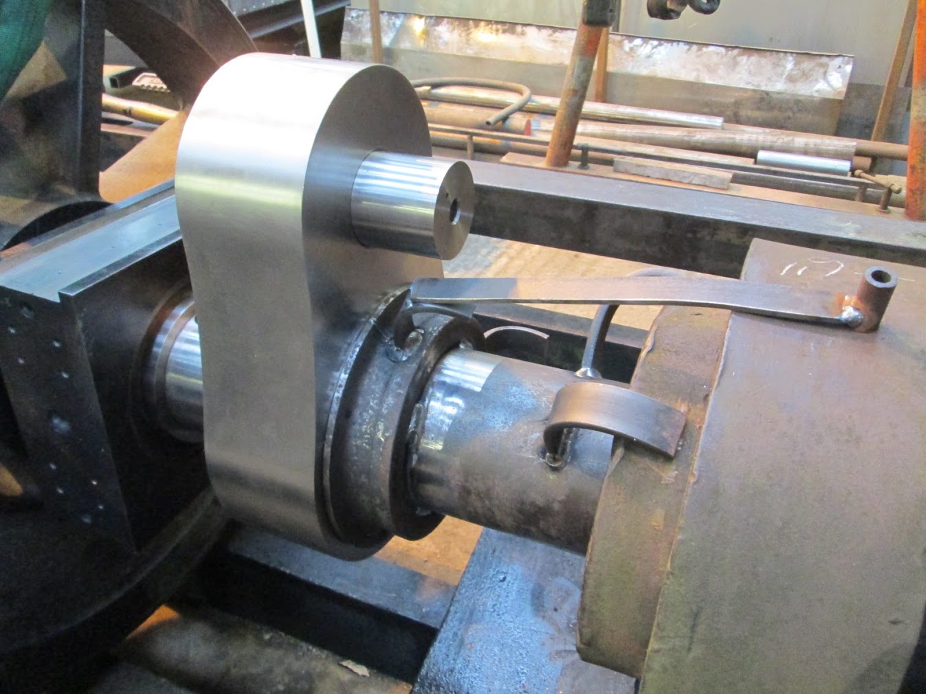
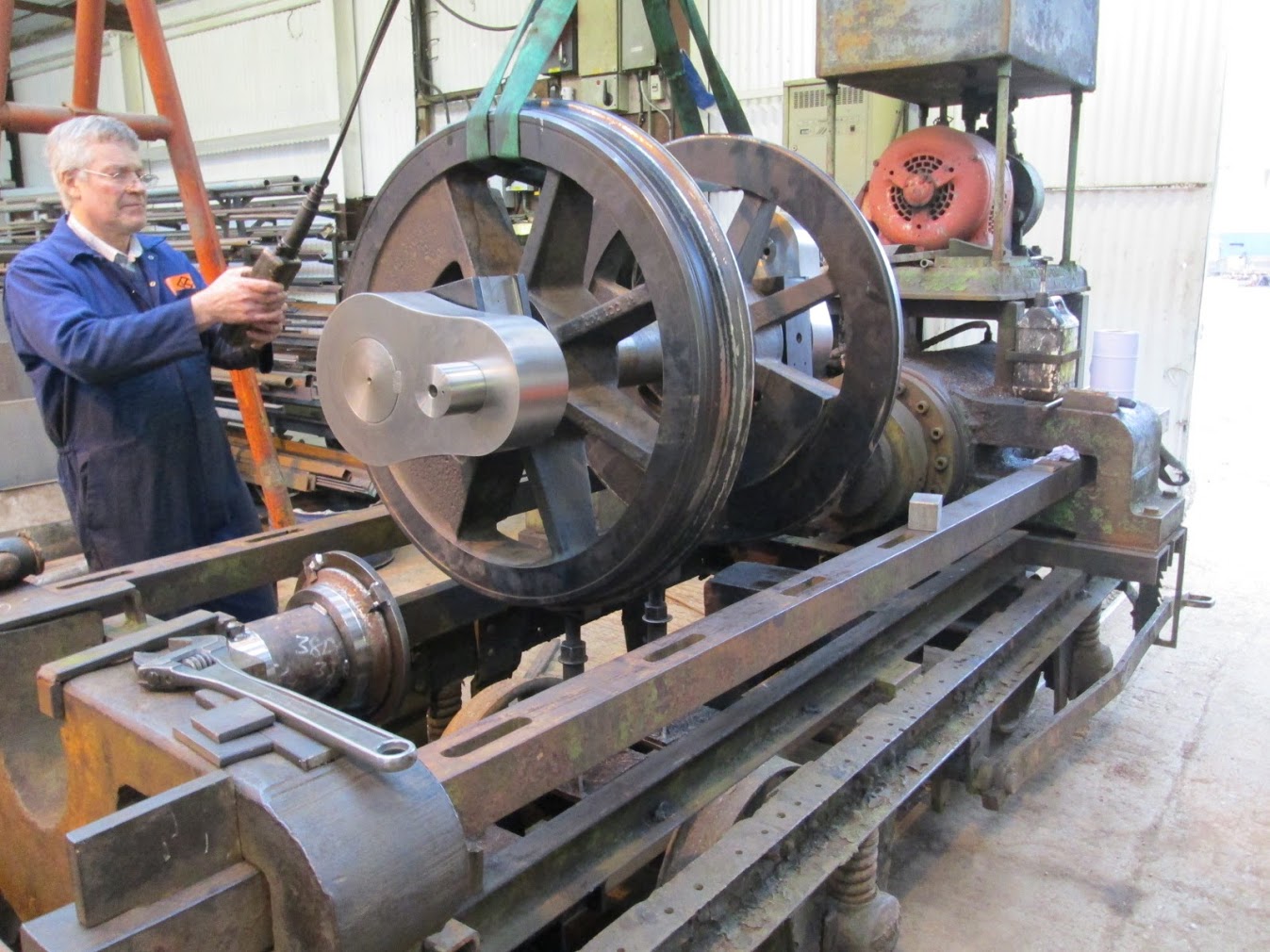
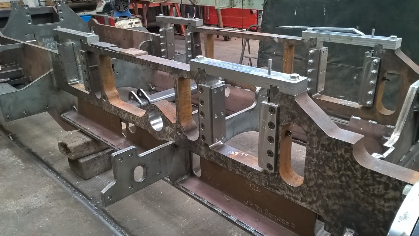
Machining the main frame member
The Front Pony Truck (from the lynformation page of the 762 club)
Cylinders completed and leak tested 23rd October 2015
During pressure testing there was very slight weepage between the outside of the valve liner where shrunk into the steam transfer port. On Cylinder B this allowed a gradual drop in pressure from 375 psi to 290 psi over half an hour (equivalent to about half a teaspoon from each end of the liner). On cylinder A there was a tiny amount of weepage, with a drop in pressure of 375 psi to 360 psi over half an hour. There were no visible signs of any leakage from any other areas on the cylinders, during this time. Having discussed this with Ian, this may self seal over time, will not be significant in use, and so is acceptable.
On the exhaust side no visible signs of leakage were seen and 30 psi was maintained except for cylinder A – front exhaust chamber. This showed a 2 psi pressure drop over 50 minutes, after rechecking connections / plugs etc. this was retested for a further 2 hours 50 minutes, with a drop in pressure from 30 psi to 25psi. No trace of any leakage could be seen. Slackening a plug, we found this was the equivalent to releasing about ˝ a thimble full of fluid over that time, so don’t believe this is significant, wherever the pressure was being lost.
Progress report up to 29th October 2015
Ian has finished checking and I have now issued the drawings for the brake stand and the rest of the braking components. The rear pony truck control assembly (the lever system that replaces the drawbar used on the original engine) has been checked and the drawings issued. A whole lot of the parts that bolt onto the frame such as the horn guides are now drawn and issued for manufacture.
The Computer Aided Design 3D model of LYN 29th October 2015
The only major item left to detail is the ashpan and that is well started. I am expecting that this will be completed in the next week or so.
There is then the task of making sure that all the fastenings and all the little items needed for the assembly are on the model, detailed, checked and issued for manufacture. The cladding has been modeled and computer files are available for laser cutting if that route is chosen. The cladding model will need updating to conform to the "as built" boiler.
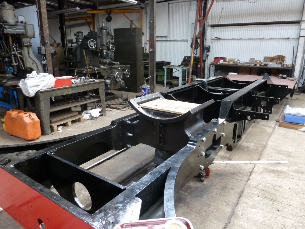
The frame for lyn is well advanced (pictures from lynformation 34)
The front pony truck is nearly finished and the rear pony truck well advanced
Progress report up to 30th October 2015
The ashpan model has been updated to the latest, simplified design and all the drawings done and issued for checking.
Progress report up to 2nd November 2015
I have been going round the design checking that all the parts that need to be designed and all the fixings etc that need to be sourced are in the assembly models and called up on the assembly drawings. This is proving to be a demanding job as I am working with some large assemblies and every change can take 5 mins for the model to regenerate which is a bit frustrating when only a split pin has been added.
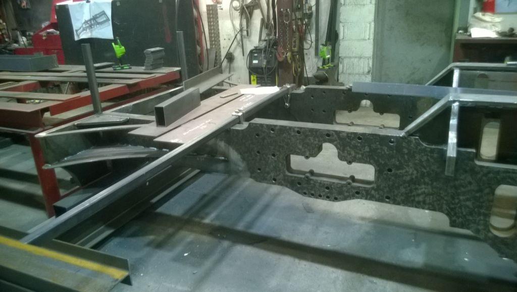
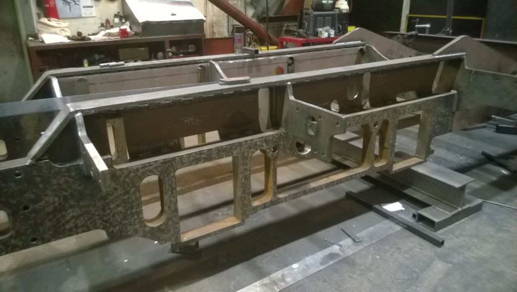
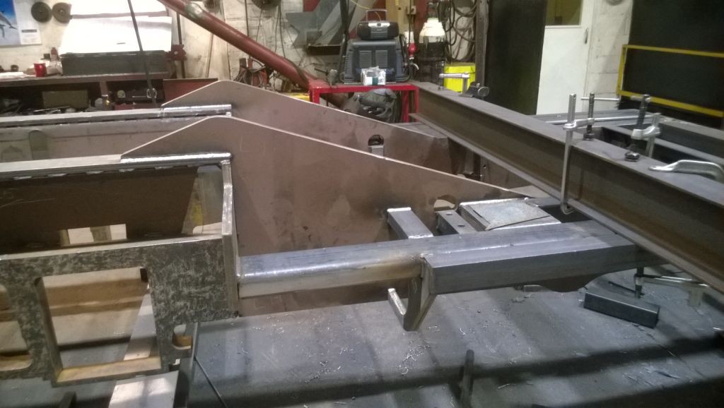
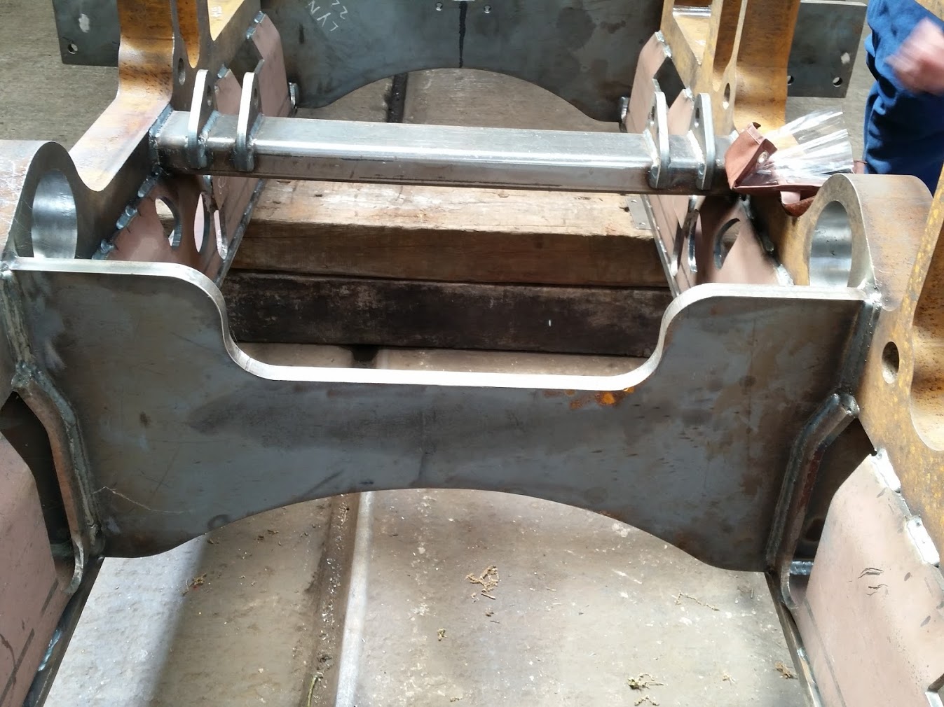
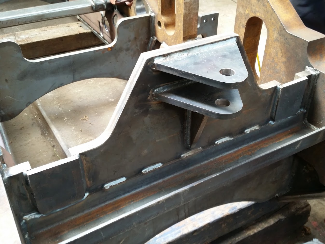
Here are a few more pictures of the frame parts being welded together. I am really encouraged to see it coming together.
Progress report up to 6th November 2015
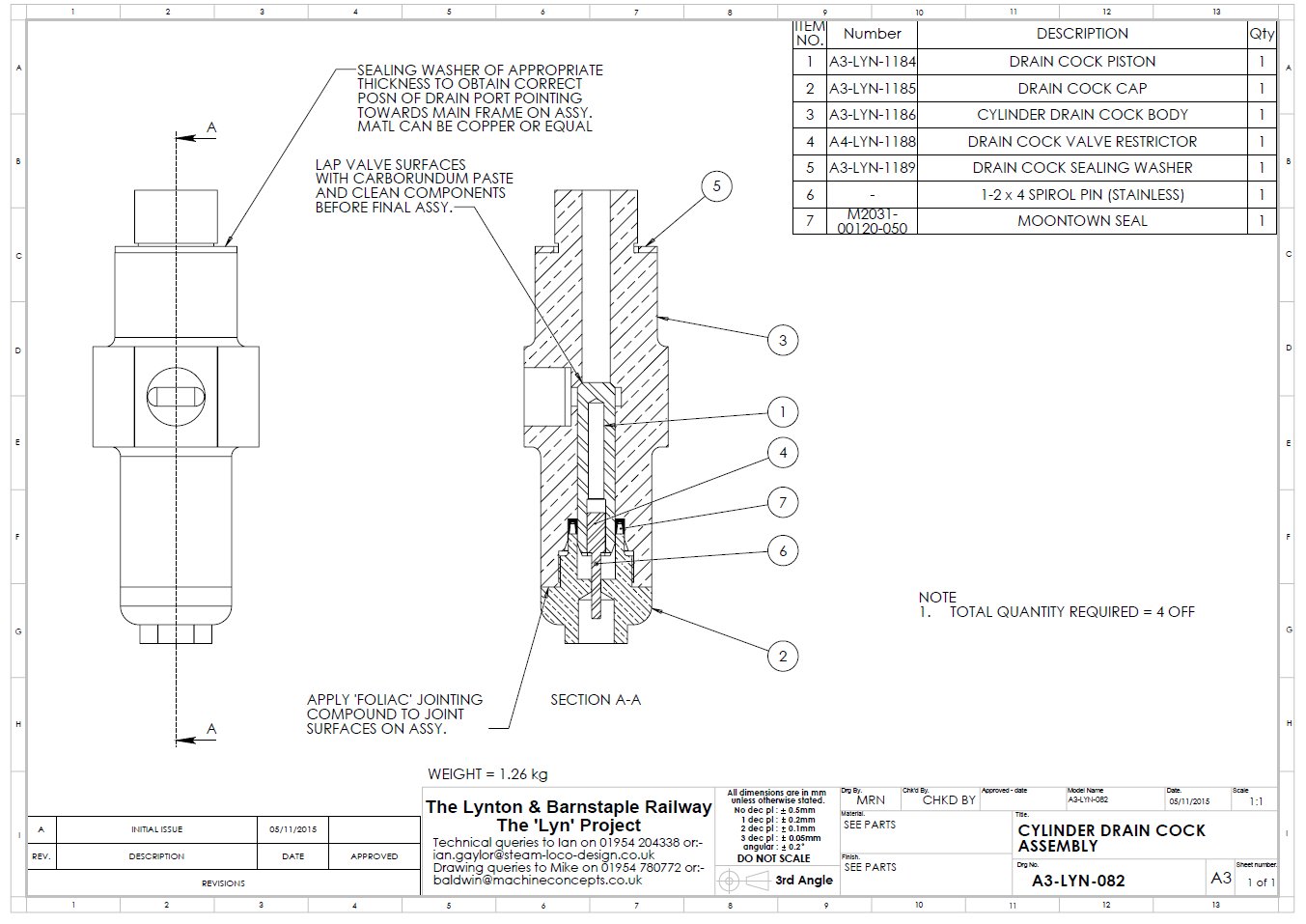
The cylinder and steam chest drain valves are now completed and the drawings ready for checking.
There is not a lot left to do. I still have some assembly stuff to do - adding fasteners etc - but the design and most of the drawings are now complete.
The frame is now complete and delivered ready for the 762 club open day. I am really relieved as the drawings for this were produced under considerable time pressure for Babcocks to manufacture and in the end they decided to not do the manufacture. A shame as the earlier work on the water tanks and the bunker was good quality.
Despite these problems A.J. Lowther & sons have done a superb job and I think that we have a better quality item as a result.
The current predicted weight is 19447.86Kg or 19.140 UK tons
The 3D model of the complete engine has 6780 components
I have done a page of pictures from the 762 club open day on the 28th November 2015. To visit the page click here
Progress report up to 11th Febuary 2016
All the drawings are finished, checked and issued. Ian and I have had a final session together to check that everything is done but really it is all now in the hands of the artisans
All that will hold up the final assembly of LYN is the gathering of enough money to finance the work and so it looks as though LYN could run this year.
Now that my modelling and draughting tasks are done and I will only be needed to answer the occasional questions, I have taken on the creation of the drawings required to produce a new ashpan for a King class locomotive. The engine is No. 6024 King Edward I. I won't be doing a blog for this work as it is only a small part of the rebuild of this loco but I will do a page of info which you can find here King 6024
Progress report up to 15th July 2016
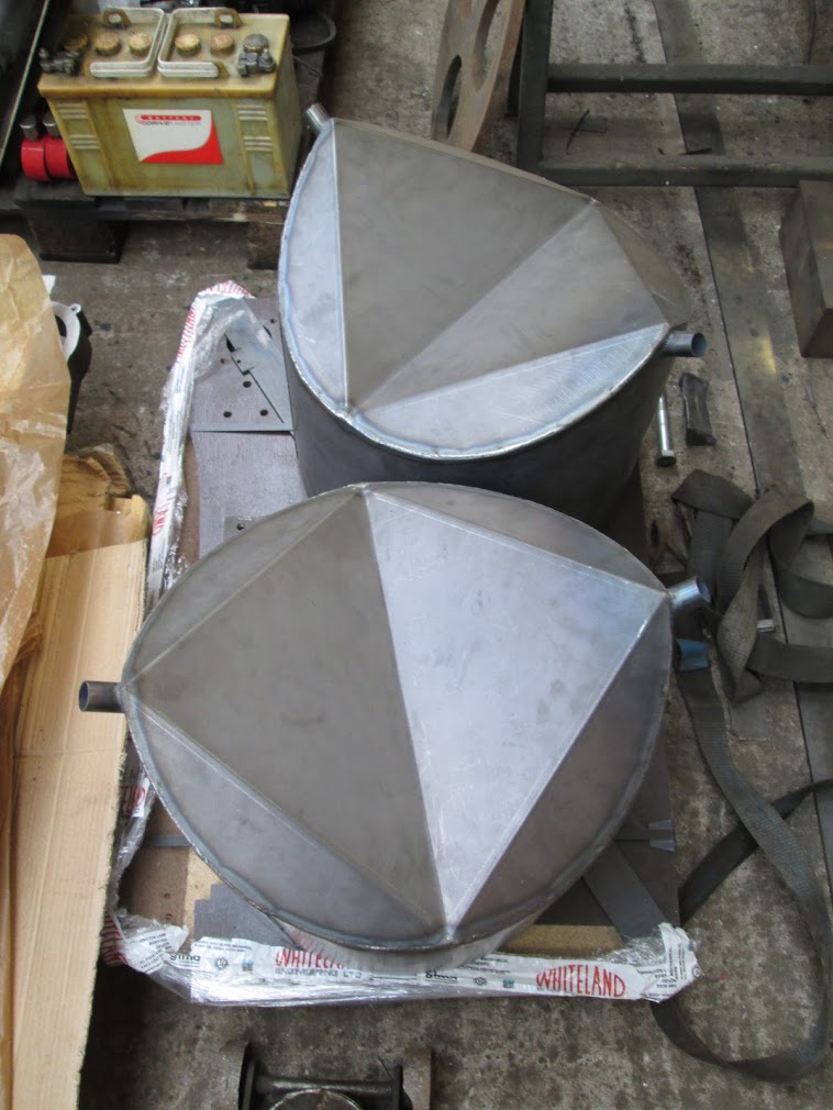
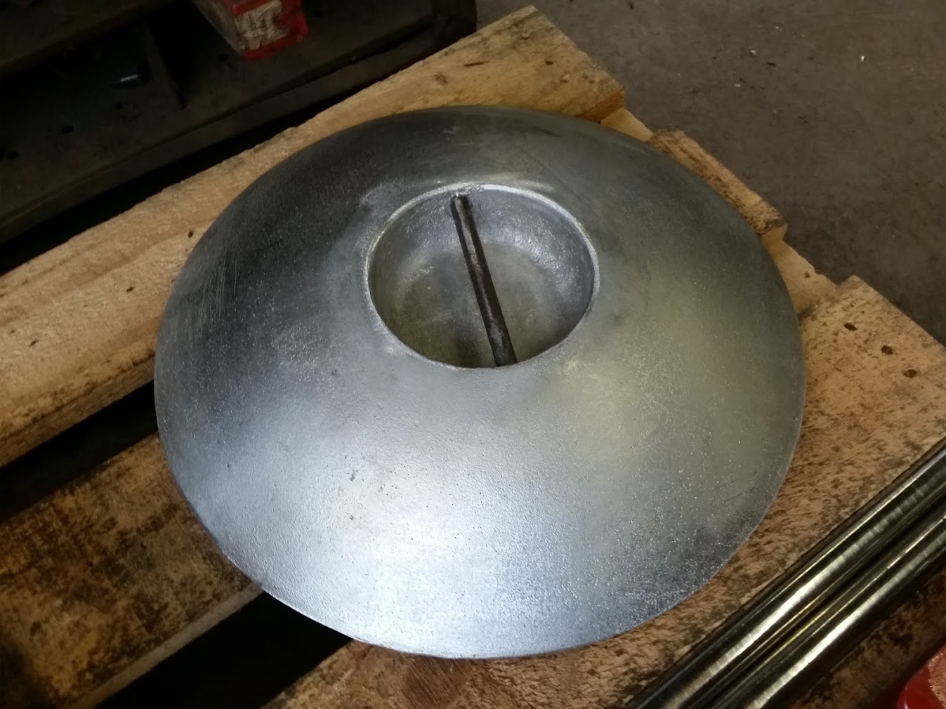
The assembly of LYN continues to progress well at Alan Keef's. The parts for the loco are now more than 95% made and the last few are already sourced. We are currently working out how to make the domes and they are in hand. The order for the cladding is about to be placed and the files for the laser cutting are ready to go. Phil at Alan Keef's has sent me some of the latest pictures of the build.
My Visit to Keefs on 13th August 2016
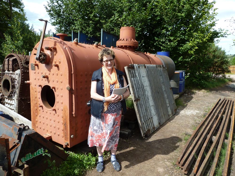
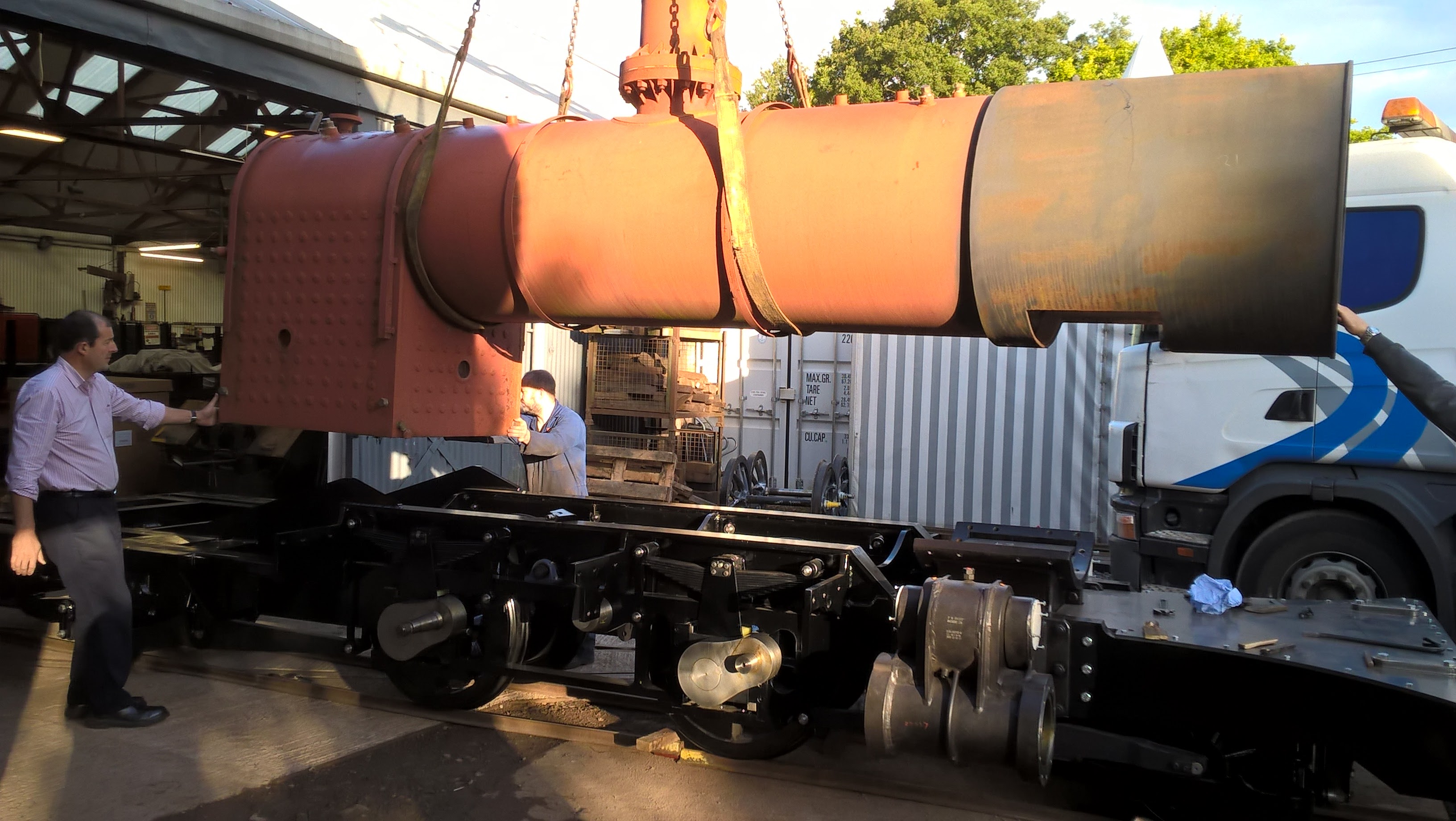
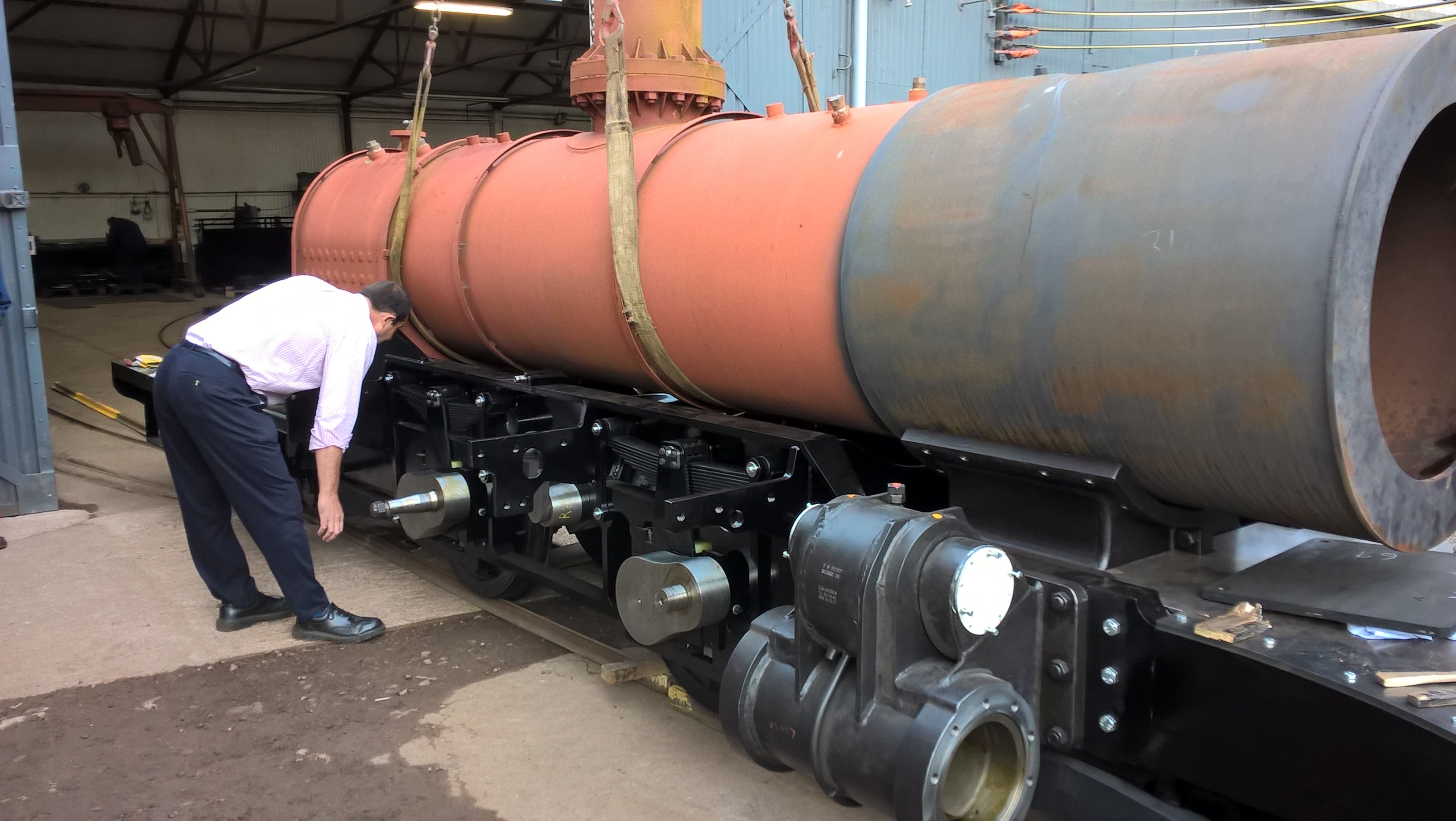
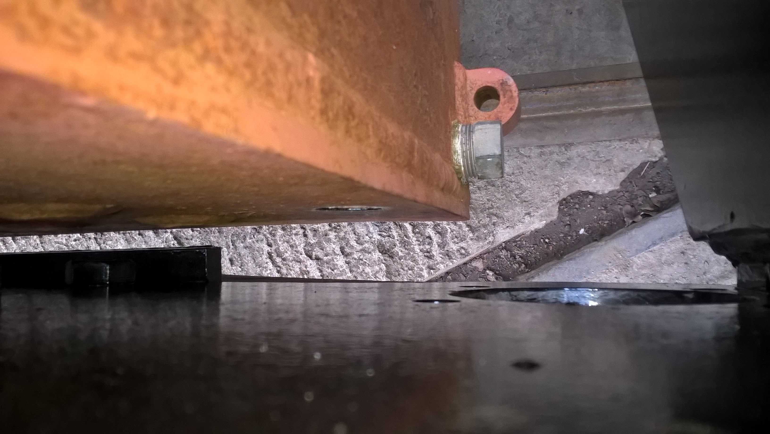
As I was visiting a friend in Stroud only 30mins from Keef's I took the opportunity to visit and talk throught the challenges of fitting the boiler to the frame. I took a couple of photos while I was there.
My Friend Karen giving scale to the boiler
Rear mounting for the front pony truck
The frame is now the right way up
Progress report up to 1st September 2016
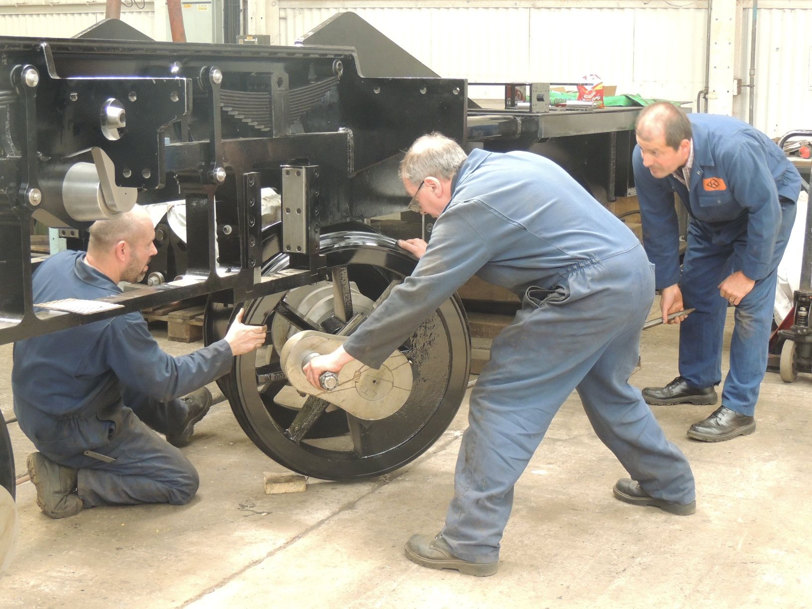
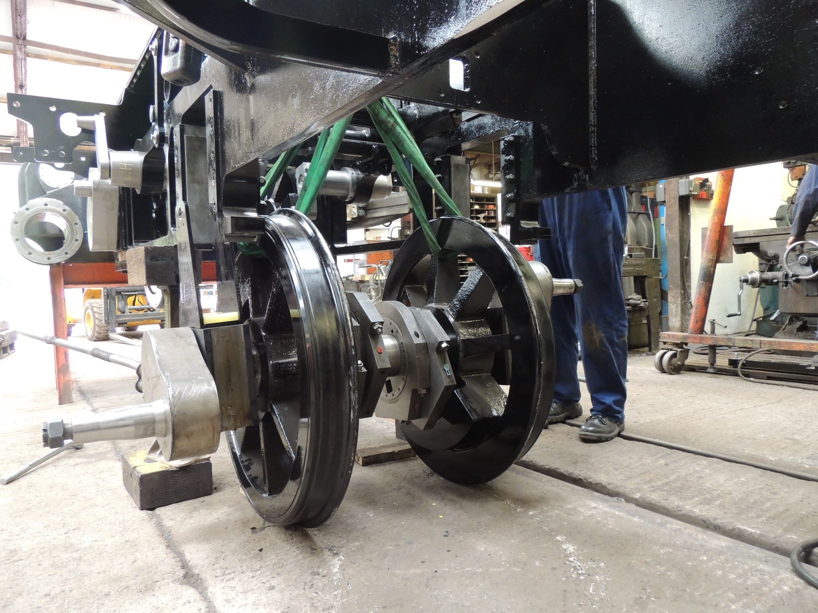
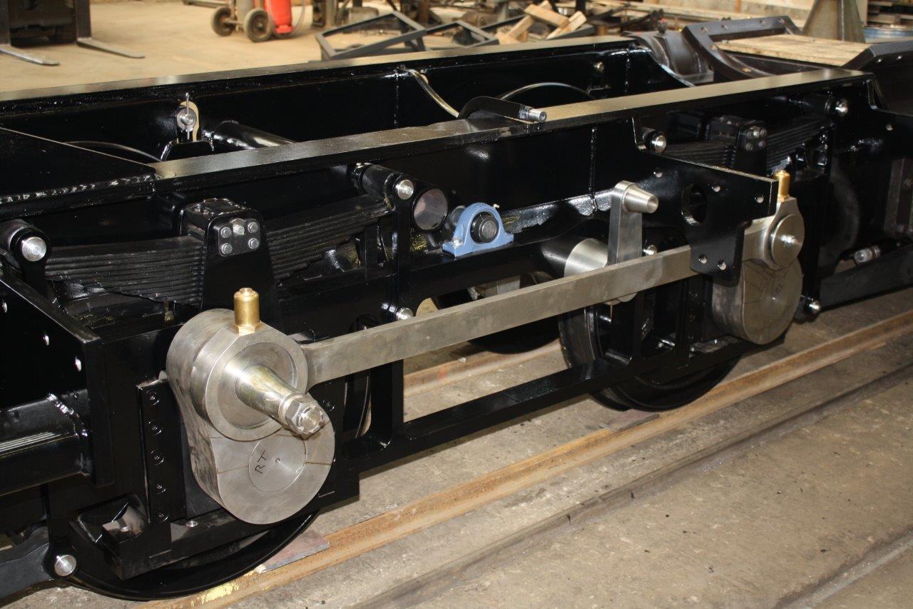
Some pictures taken by Peter Best when the main wheels were fitted
Progress report up to the September 17th 2016 Keef's open day
Some pictures taken by Peter Best
One interesting thing is that the loco has needed to be chocked against inadvertant movement as it is so free rolling that even leaning against is will set it moving. Rolling bearing rule!!
Progress report up to the September 26th 2016 boiler fitting day
Some pictures taken by Phil Kent
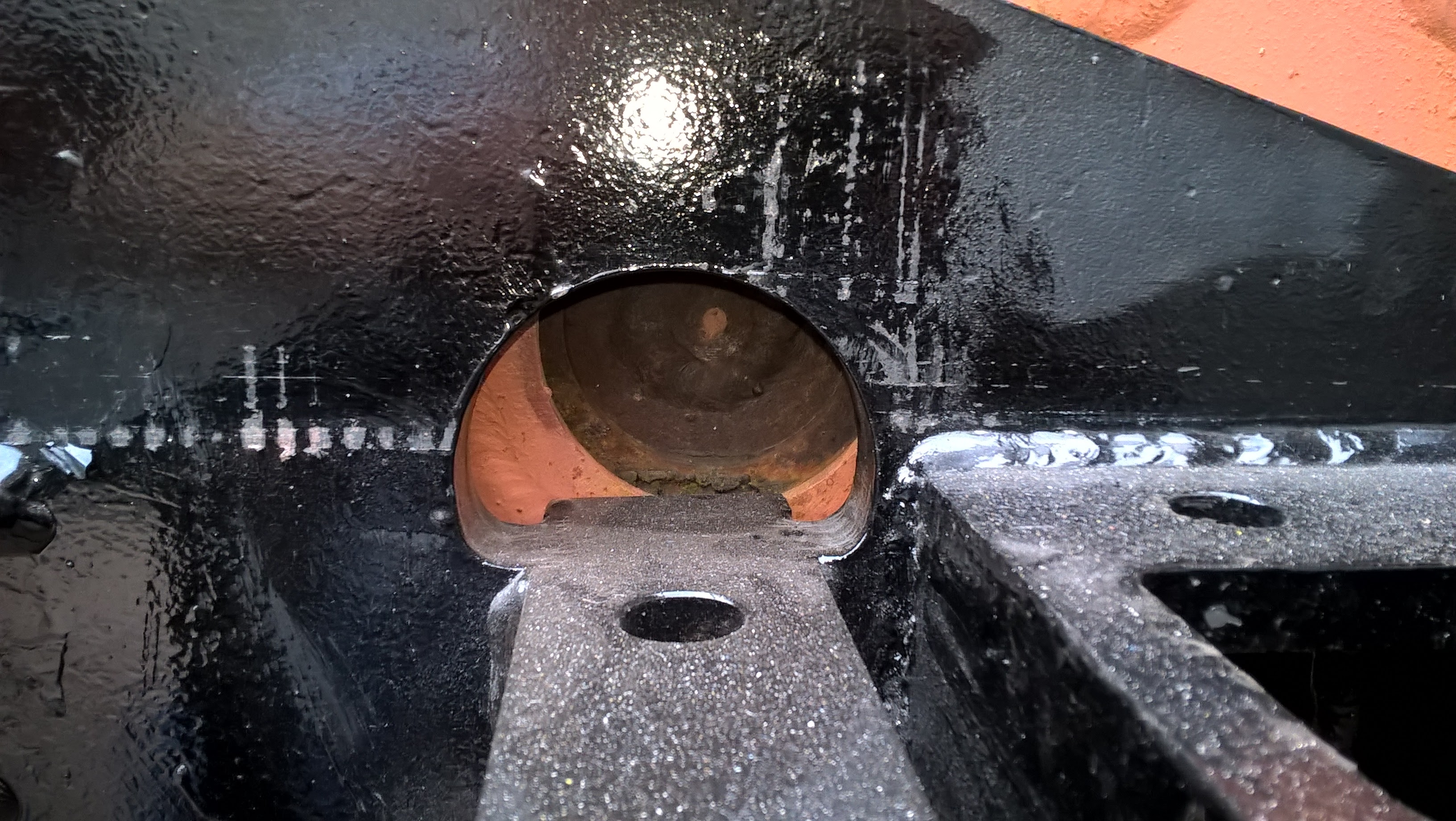
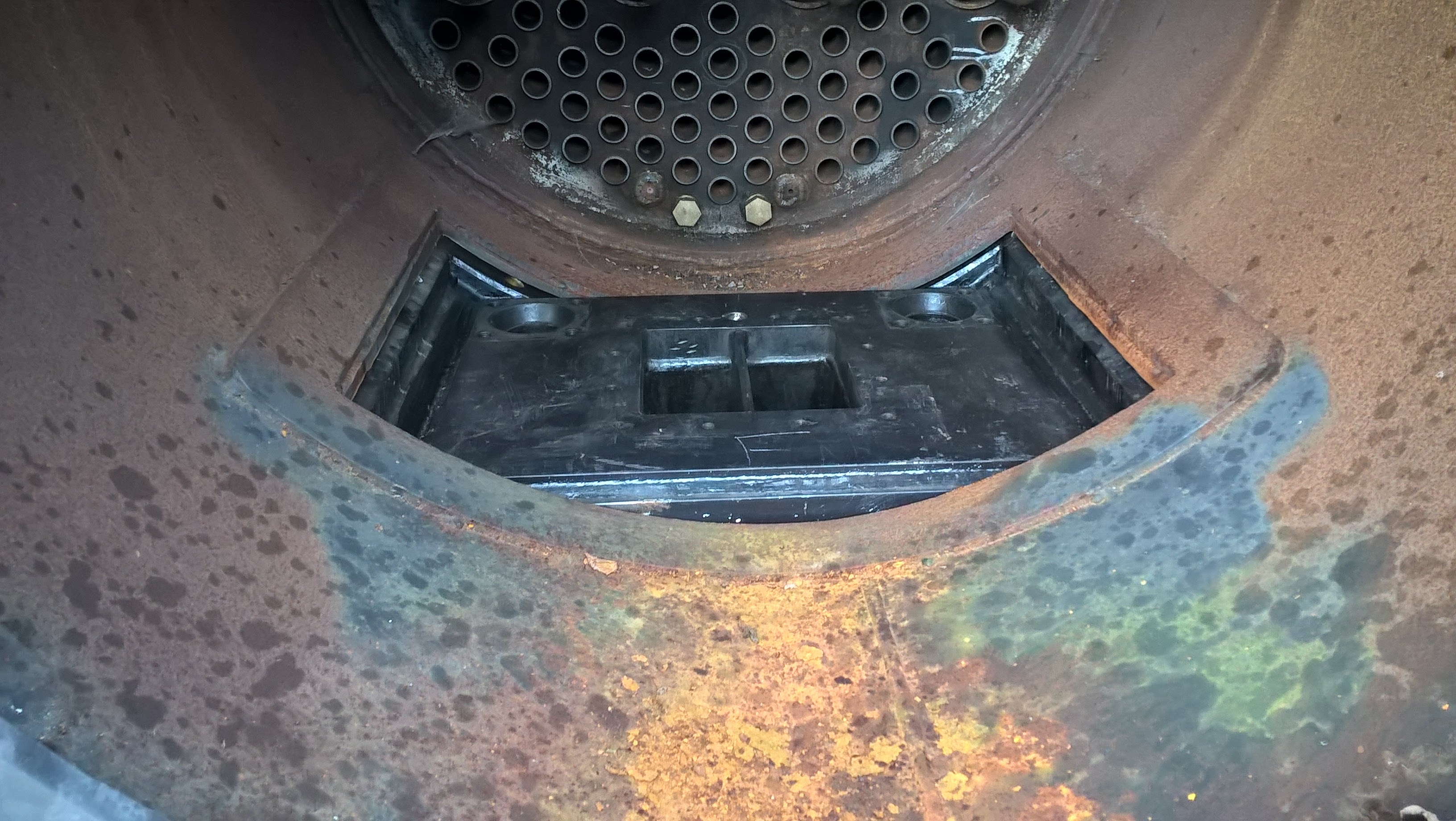
The boiler does fit - well, almost. The boiler with the smokebox in place is about 15mm too long compared to the drawings and 3D model and the dimension of the chassis is a bit short (about 10mm). Phil will cope with this by cutting a bit more from the hole in the bottom of the boiler where is locates on the saddle which will make the firebox area correctly positioned. We also have to do a small mod to make room for the removal of the drain plugs but again this shouldn't be too stretching.
Progress report up to the October 21st Fitting the inside valve components