
Progress log page 2

|
|
Progress log page 2 |
|
The chassis assembly has now been updated by adding the motion, valve gear, the saddle and the cylinders.
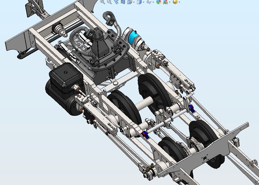 This is the latest jpg of the loco chassis. |
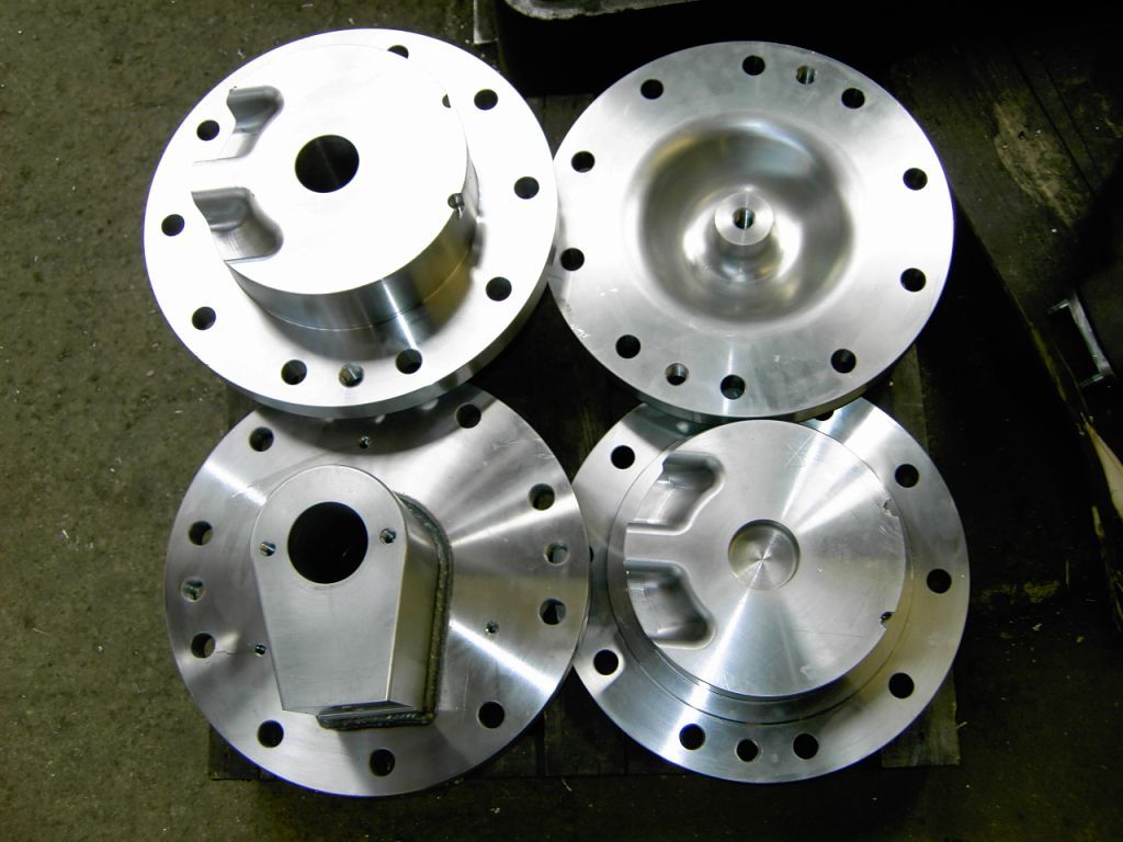
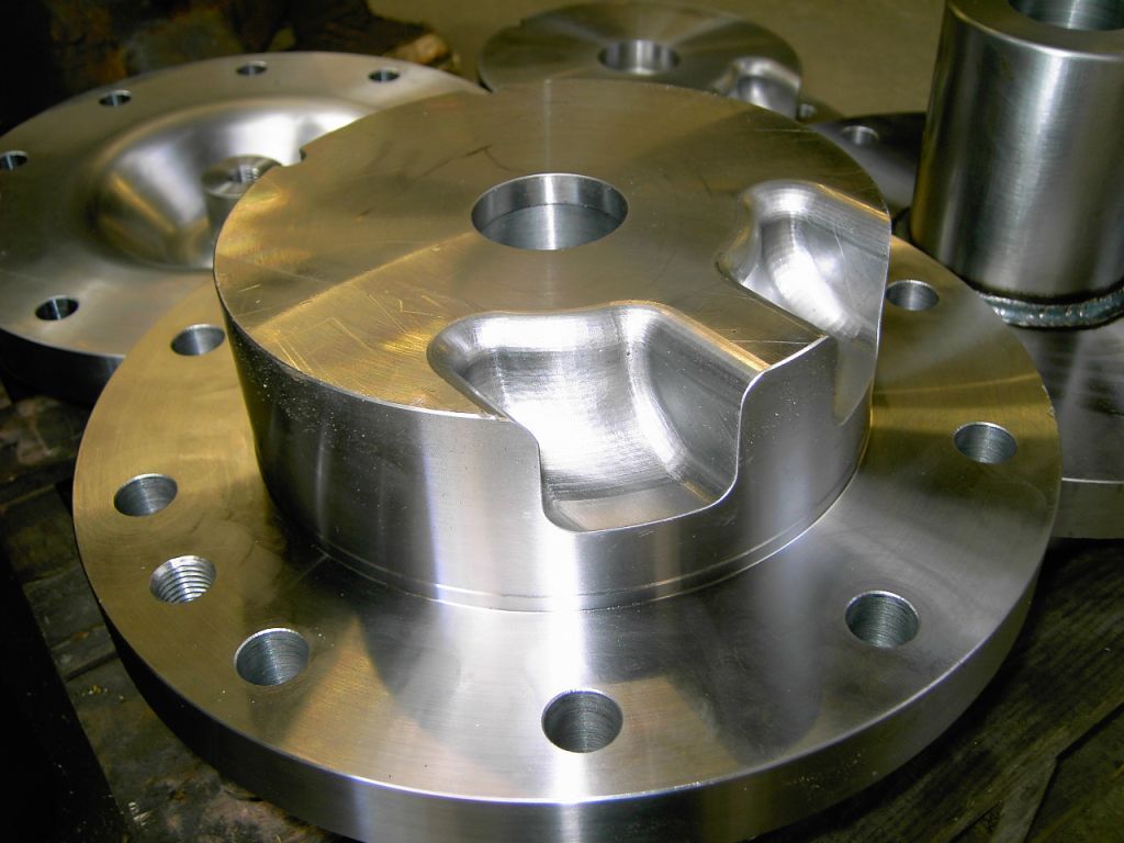
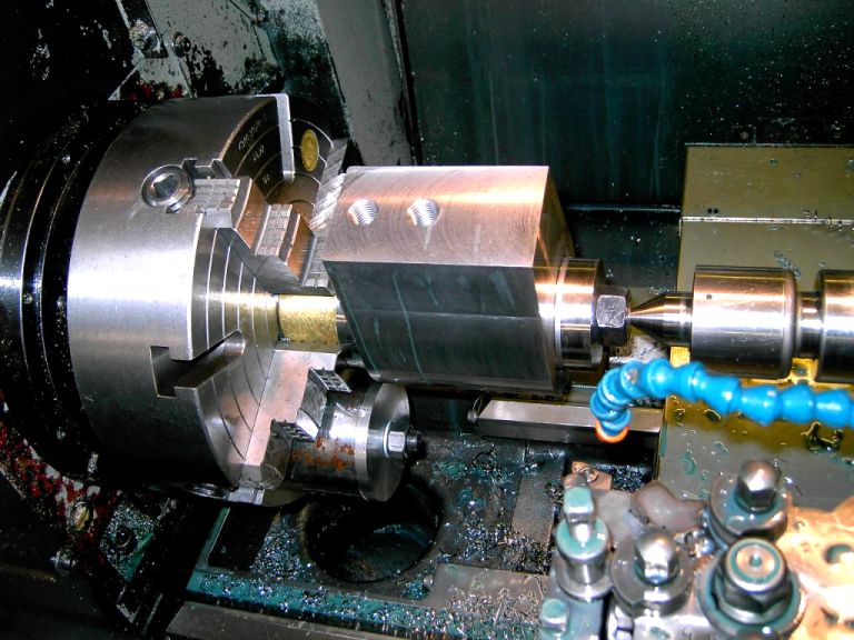
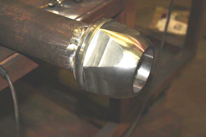
The manufacturing drawings for the valve gear and all its bits are mostly completed and waiting for checking. Ian has completed the design of the reverser and I have now modelled it up and added it to the engine main assembly. Ian and I are having a design review tomorrow to iron our a few things that the modelling has thrown up. Ian has started designing the axle boxes and I am looking forward to getting them modelled. I have just today received some pictures of the work in progress at Alan Keef. I especially like the picture of the valve turning and am quite jealous of the chap doing this work.
 Machining the valve body. |
 The finished valve end caps. |
 The finished cylinder end caps + other parts. |
 The regulator gland. |
 The reverser assembly. |
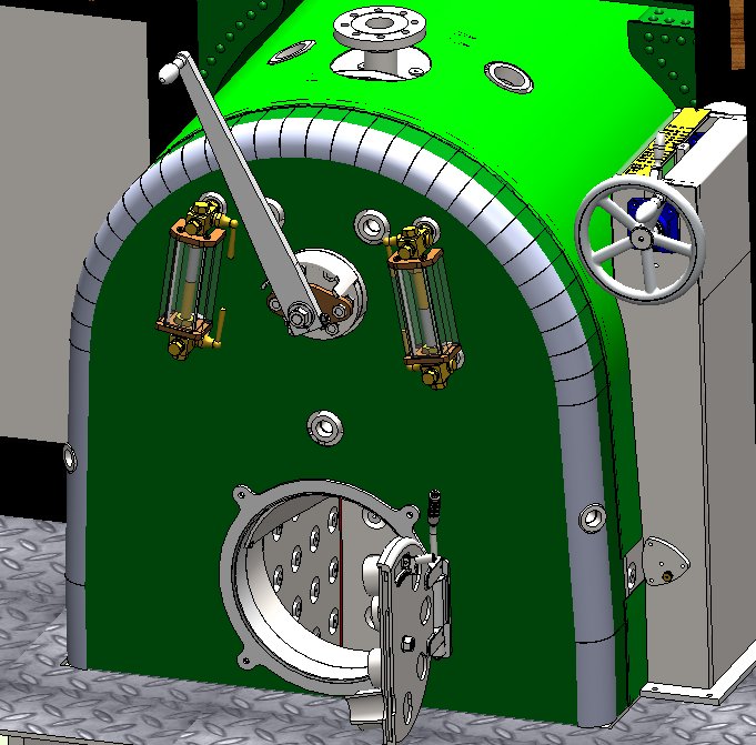
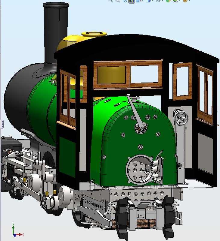 The reverser in the cab. |
I am busy completing the detail design of the reverser and I am getting on with the detailing of the manufacturing drawings. I have also updated the valve mechanism with the addition of a lubrication system for the dieblock. This takes a feed from the oil distribution unit and drips it into a trough feeding a pipe that directs the drips of oil onto the top of the dieblock.
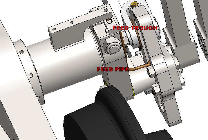 Dieblock Oiling. |
 Complete model of the boiler. Click on the picture for a photo of the real boiler. |
Ian Gaylor has finished the axlebox design layout and passed it to me the . I have finished modelling the main components and the chassis assembly has the axle boxes and the hornblocks fitted. As the areas are finished the frame is being updated to the latest geometry. We have a major design review meeting next week and I am aiming to have all the areas that we have designed fully modelled so that we can get any tricky areas reviewed.
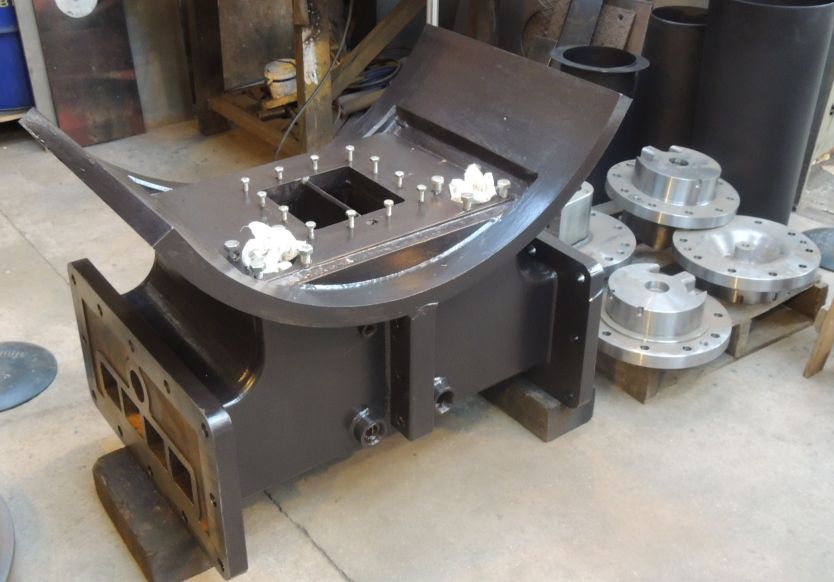
 frame with the axle box. |
 Lyn's frames. |
 Exploded view of the axle box showing the bearing. |
 Section through the right side driving axle. |
 Section showing the high grip wheel rim profile based on the work of Engineer Livio Dante Porta. click on the picture for a more detailed description of how it works |
The main axles are now assembled and all the parts modelled. I have started the detail drawings for these. the final shape for the flycranks is sorted and the model now reflects the latest shape.
 trailing axle assembly. |
 leading axle assembly. |
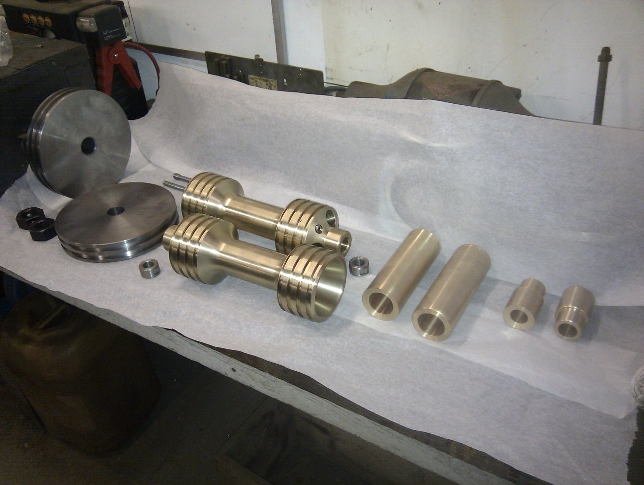 piston and valve parts. |
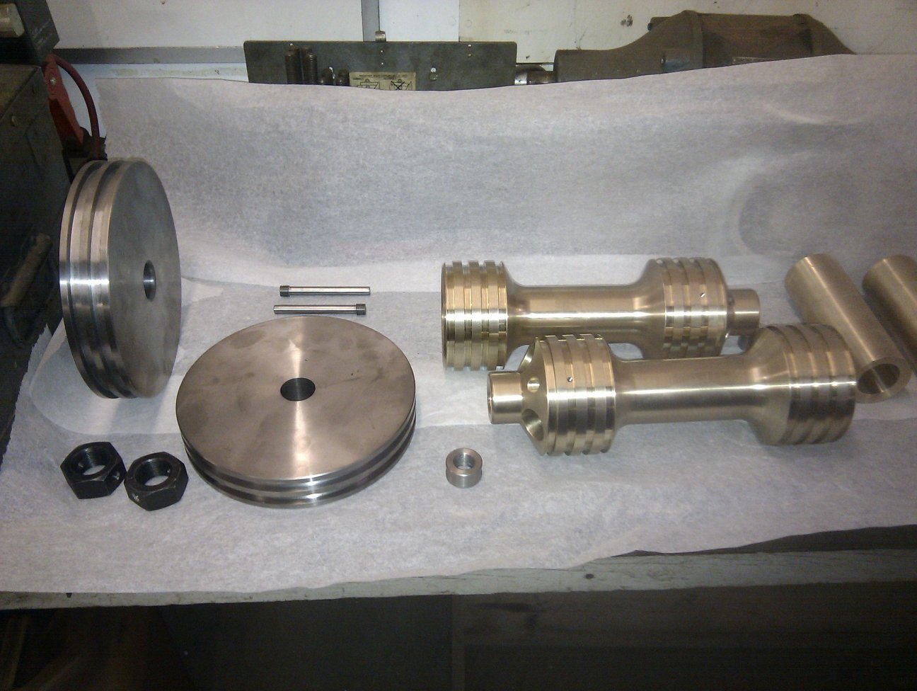 piston and valve parts. |
Not much new to report. I am updating the watertank models and drawings. These were some of the first parts modelled back in march 2011 and needed final updated to take account of all the parts now completed and fitted to the main modeled assembly. There are a total of 3864 components assembled together to make the engine so far. This number includes all the fastenings, pins, circlips, boiler stays, and more than 700 unique components that will be manufactured.
The drawings for the water tanks have been completed and issued for manufacture.
Andy Bennett has completed the hydraulic testing of the boiler and is about to start the superheater manufacture. He has asked me to see if I can simplify the manufacturing by making the header as a casting. I have looked into this and it is much too expensive mainly due to the pattern cost but, whilst I was looking at this, I realised that the existing design of a single component made from parts with a lot of welding could be re-designed as 2 chambers that clamp together when assembled to the boiler and that this makes it possible to make the design much simplier and the welding much easier to do.
Another area of the superheater that was causing difficulty was the actual tubes that go into the boiler flue tubes. The company, Willingale Tubes, had found that the original design had too many bends close together and to solve this they were proposing to weld together short pre-bent lengths. This would make the job much too expensive and I could see that it would be possible to achieve the same result with just single bend. This sort of design exercise is made much easier because of the use of 3D CAD modelling tools.
Here are a few pictures showing the old and new design:-
 Original Header Design. |
 New design Header Front Chamber after welding. |
 CNC Machined main body. |
 New design Header Front Chamber after final machining. |
 Exploded view showing the 2 chamber design. |
 New Design for Superheater. |
 superheater fitted to boiler showing simplified tube bending. |
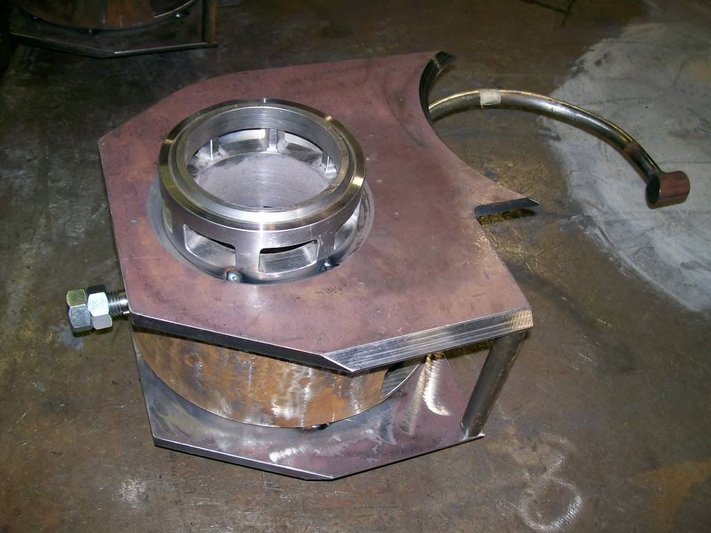
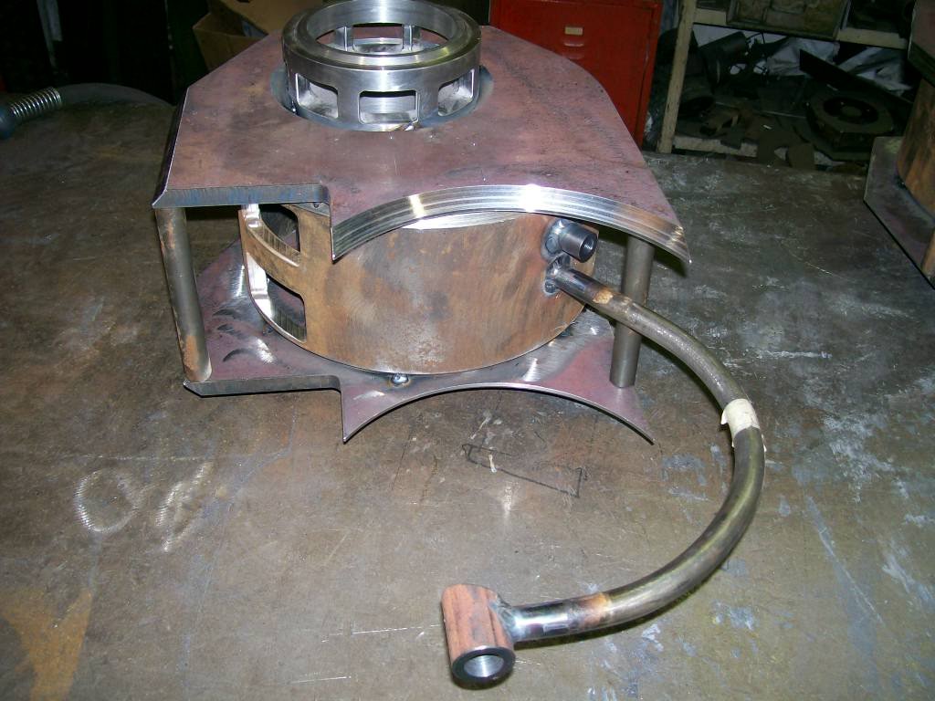
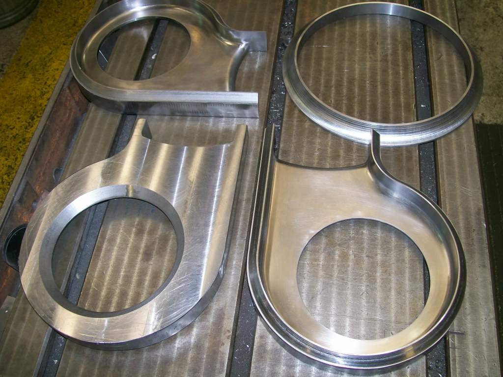
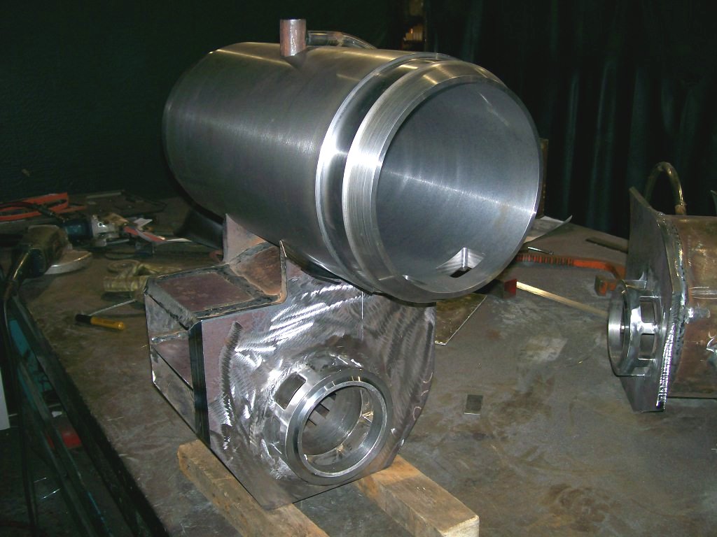
Probably not the latest information but here are some more pictures of finished parts from Alan Keef
 Finished Cylinder End Covers. |
 Cylinder End Cover Port Machining. |
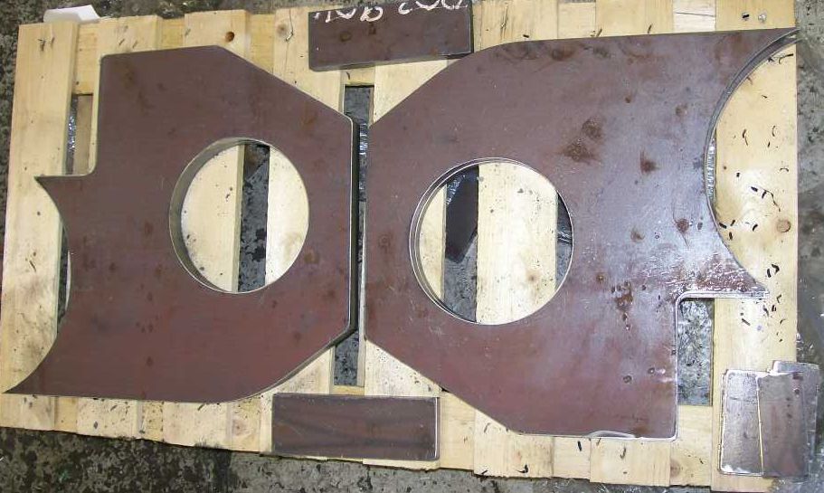
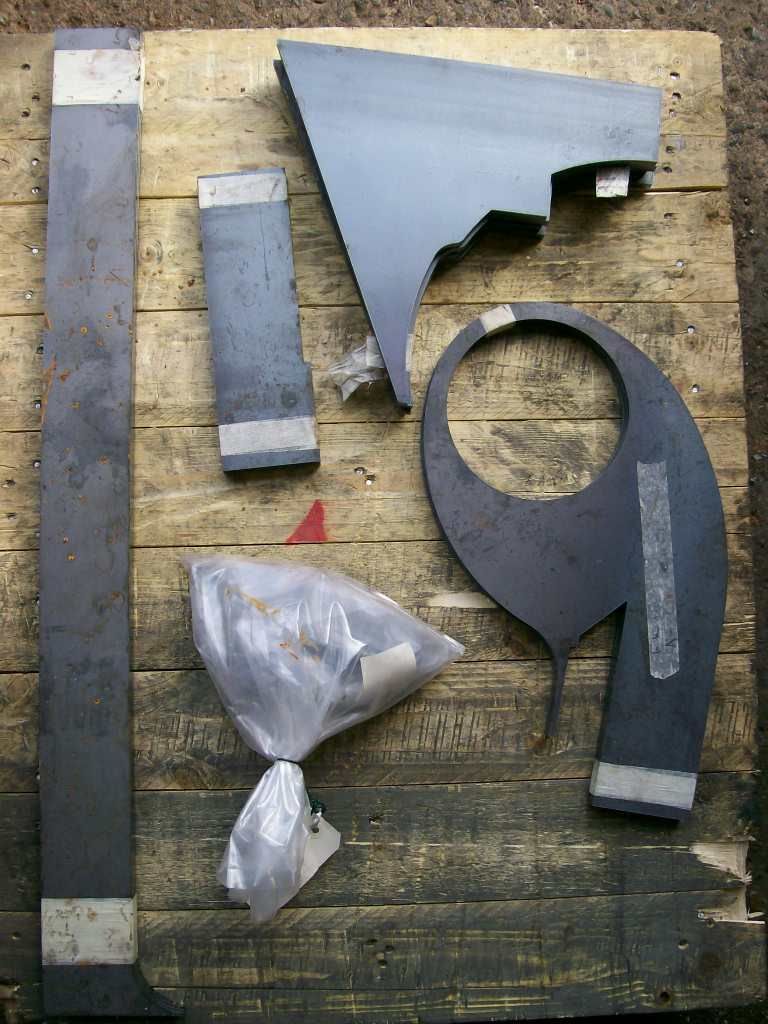
 Finished Cowcatchers Covers. |
 Machining the Piston Rod Bearing Blocks. |
Further improvements have been made to the superheater design. This time the clamping of the ball ends to the header has been simplified by using a separate collar (the purple things in the picture below) to pull each ball into its seat and a simple block bridge to apply the force. This has solved a potential conflict between the centres of the header and the centres of the clamp and also made the welding of the ball end to the tube easier.
 detail of the clamping of the superheater to the header. |
 section through the tube mounting Machining. |
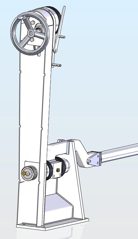
I have now almost finished the redesign of the reverser. The original design incorporated a toothed belt to both transmit the drive from the handwheel to the leadscrew and to create the 2:1 gearing to enable the use of a leadscrew that wouldn't back-drive even under the most extreeme loads that the valve mechanism could apply (flat out with a complete failure of lubrication). Ian has now finished a redesign and I have modelled it up and it looks good. The drive is now carried by a pair of bevel gears giving the 2:1 ratio and the indicator is on the top of the unit in a more traditional manner.
 Reverser driver side view. |
 Reverser mechanism. |
 Reverser in cab, driver view. |
No New pictures this month ( I have updated the picture above to show the gauge frames and protectors). The reverser design is now approved and I am starting the detail drawings ready for manufacture. I have provided DXF (a 2D data file used for cutting flat sheets) files for the bunker to the potential manufacturer and STEP (a 3D data file used to provide the accurate geometry to the CNC program) files to the super heater chamber manufacturer. I am expecting the checked valve gear drawings back from Ian shortly and will get them updated and issued soon. I have also been supporting the Boilermaker as he fits the smokebox and the crinolines. The gauge frames have been added to the boiler backhead
I am working on the design of the cylinders to see if I can design out some of the manufacturing cost and trying not to sacrifice any significant performance in the process. It is really encouraging to see some of the major components coming together.
 |
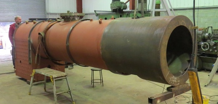
The boiler has now been to Woody Bay for its first visit and looks superb. The major part of the welding on the superheater headers is completed. The 2 chambers have been tack welded back to back while the front and back plates are welded in. This ensures that the headers don't distort when the welding is done. The units will be stress relieved before the tack welds are ground off and so should remain flat. The parts used to clamp the superheater tubes to the headers are finished. The pictures show the parts but for the correct assembly please refer to the pictures of the superheater model above.
Also finished is the front end of the drypipe that connects the front of the boiler to the superheater header
 Original port design. |
 Simplified port design. |
I have put the detailing of the reverser on the back burner for a while as there are some more pressing tasks needing attention. It has been decided that the steam dome needs to be split and achieving this entails quite a lot of changes in addition to the obvious dome split. The mounting for the regulator valve has had to be lowered to place it below the split line. The linkage for the regulator has had to be shortened. The trumpet on the top of the valve has been extended to compensate for the lowering of the valve.
One major change has been to the supporting of the regulator shaft. Andy Bennett wondered if it might be possible to support it from the drypipe elbow and I have now produced a design that achieves this.
 Original steam dome design. |
 Split dome design. |
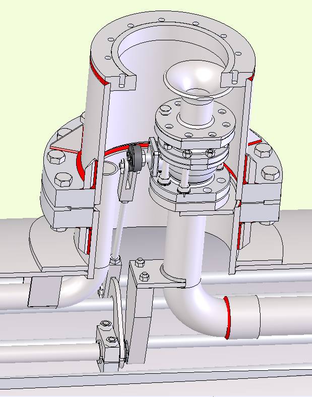 Split dome and internals. |
The valve gear and the motion are now checked and released for manufacture. The superheater headers are welded up and, having been stress relieved, are being machined and the superheater tubes are being welded. The boiler steam dome has been split and the flanges are welded on. No pictures yet but I will post any that I can prise out of Andy Bennett.
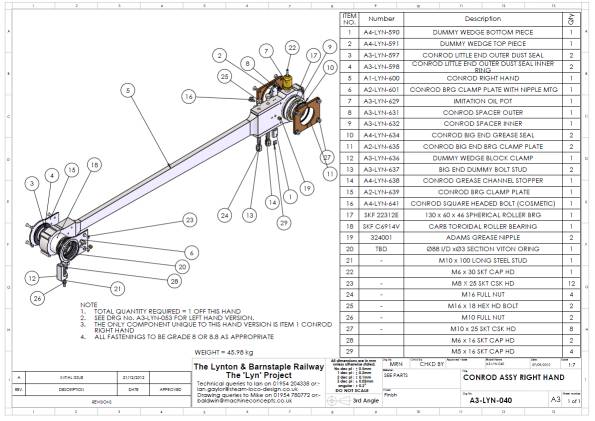 Connecting Rod Assembly Drawing. |
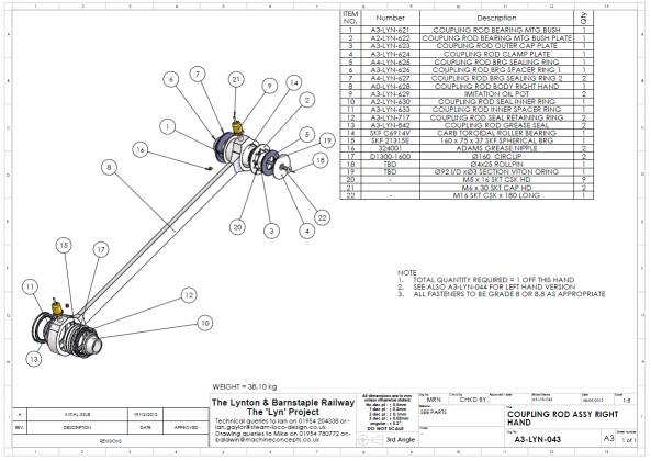 Coupling Rod Assembly Drawing. |
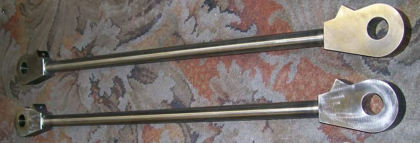
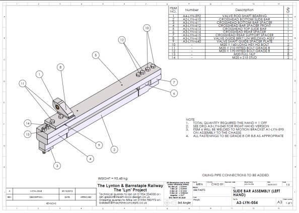 Slidebar Assembly Drawing. |
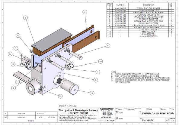 Crosshead Assembly Drawing. |
The driving wheel and axle assemblies and the reverser assembly are now detailed and issued for checking.
I have finished the work to suck some of the cost out of the cylinder assemblies and we have a meeting mid December with the likely contractor for the manufacture.
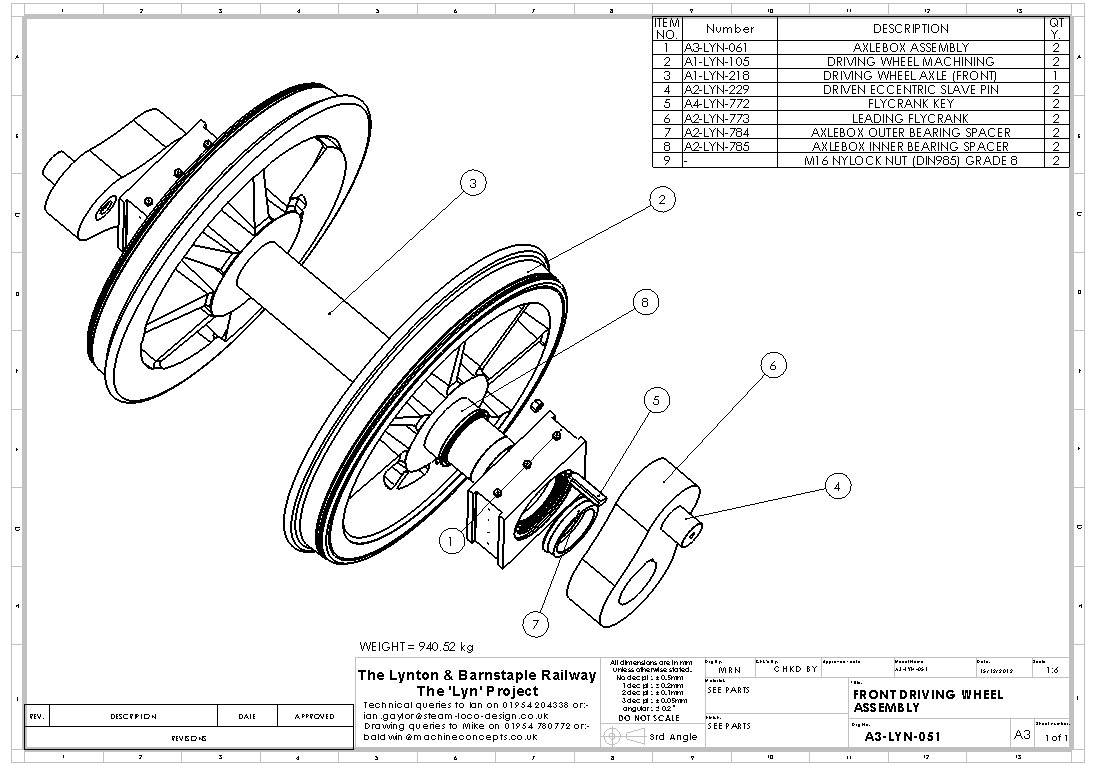 Front wheel set assembly drawing. |
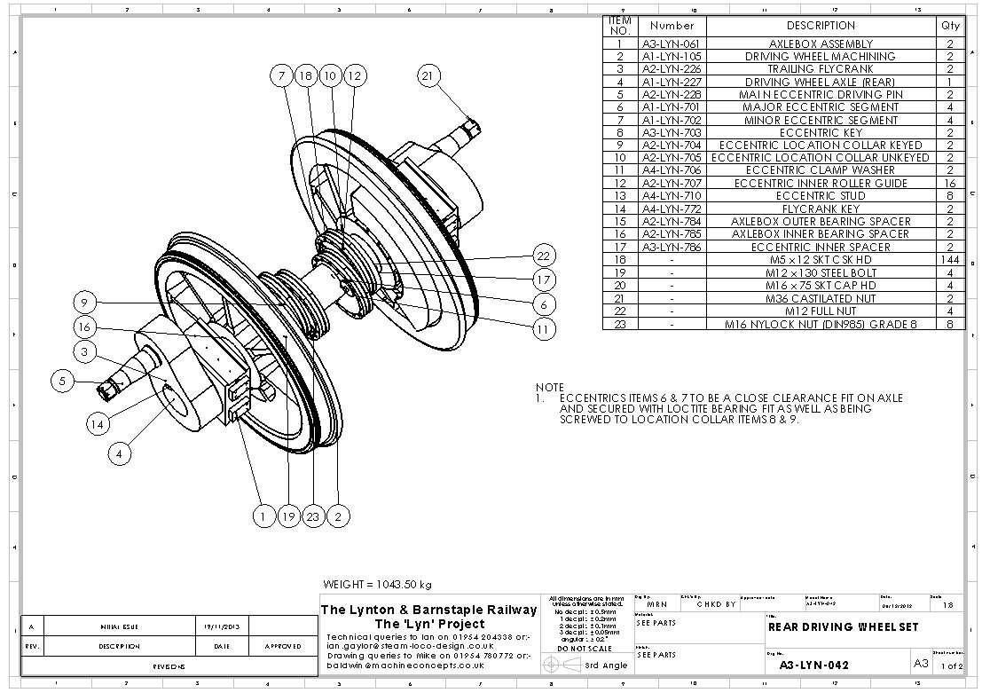 Rear wheel set assembly drawing. |
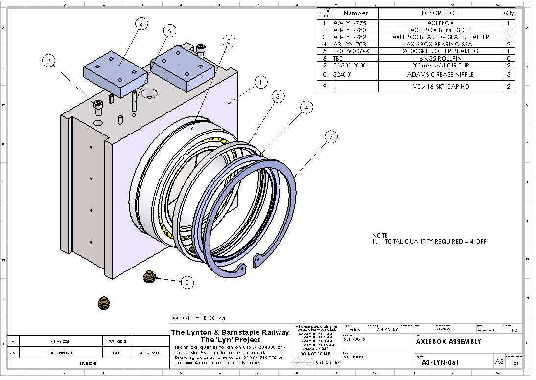 Axle box assembly drawing. |
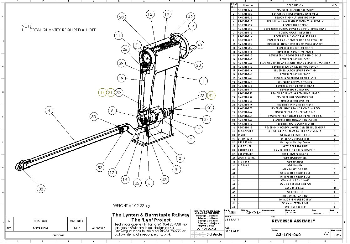 Reverser assembly drawing. |
We (Ian Gaylor, John Scott,Peter Best and Mike Nelson) visited FW Frost Ltd who will be manufacturing the cylinders for LYN. This is one of the trickier assemblies and we have a lot of confidence that Frosts will do an excellent job. They have done similar locomotive work before. We are expecting the cylinder assemblies to be delivered in June 2014.
John Scott is the ICP (Independent Competent Person) for the LYN project and ensures that all the eyes are dotted and the tees crossed.
The boiler continues to move forward. The steam dome has been split, the drypipe and the J pipe are now fitted and the regulator lever and shaft assembly have been test fitted. The headers for the superheater are now finished and ready to fit.
I have the Vacuum Gauge, the whistle and the Drivers brake unit to model and add to the assembly.
I think that we (the design team) will be finished the design and the detail drawings by the end of March 2014 (subject to the usual caveats!). and from then the only thing holding back the build will be the funding.
Peter Best visited Andy Bennett last week and took a few pictures.
 Boiler with the dome split and the crinolines added. |
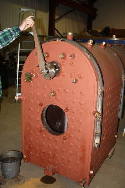 Boiler backhead and regulator lever. |
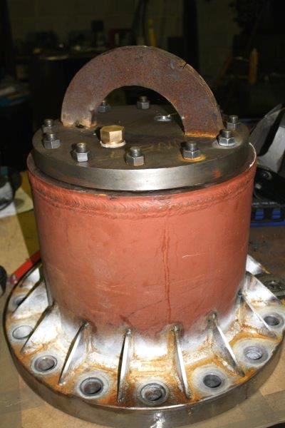 Steam dome (on the top is a temporary lifting loop). |
 Drypipe before fitting. |
 Superheater headers. |
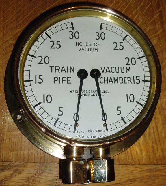 Vacuum Gauge, a gift to LYN from Roger and Sara Davies. |
 Whistle. Castings for this were donated by The Puffing Billy Railway in Australia. |
The axle assemblies and the axlebox assembly have been checked and the manufacturing drawings completed and issued for manufacture. The trailing axle has been a tricky assembly as it also carries the valve eccentrics and it is vital that these are assembled correctly to ensure the valve events are as close to perfect as possible.
The regulator and all its connections has been successfully assembled by Andy Bennett and it looks good. It has certainly justified the splitting of the steam dome as I doubt that we could have assembled it through the top flange. Andy has sent me a couple of pictures of the regulator all assembled.
The superheater headers have been successfully fitted and the superheater tubes are now being made. I have designed a welding jig in co-operation with Andy Bennett and the main part has been detailed and issued. I have a couple of secondary jigs to make to help locate the tubes when the return castings are welded on.
 regulator assy. |
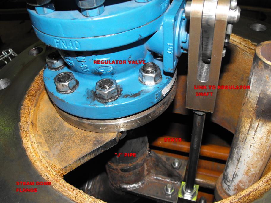 Close up of the regulator in the steam dome. |
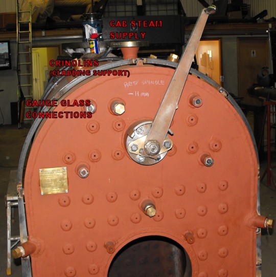 Boiler backhead and regulator lever. |
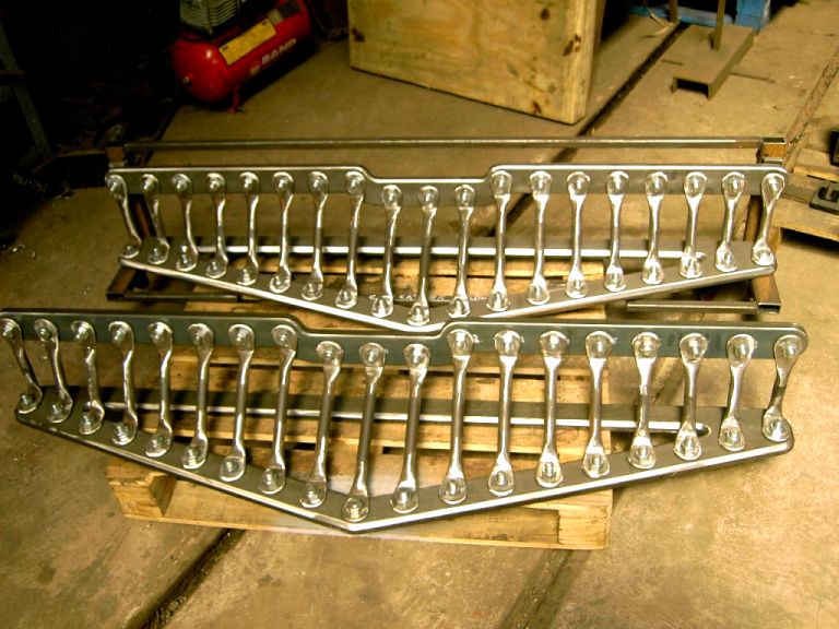
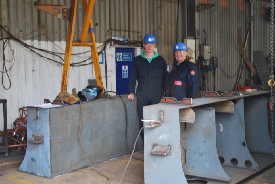
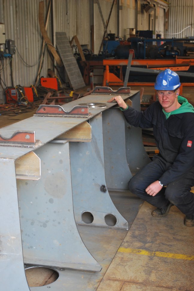
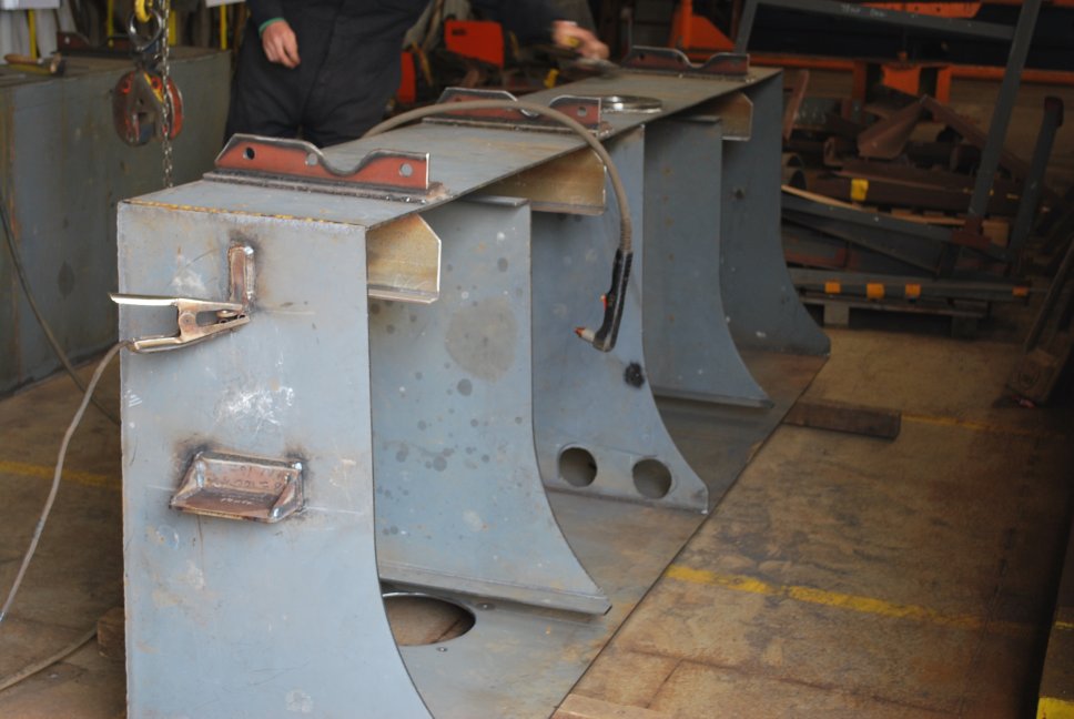
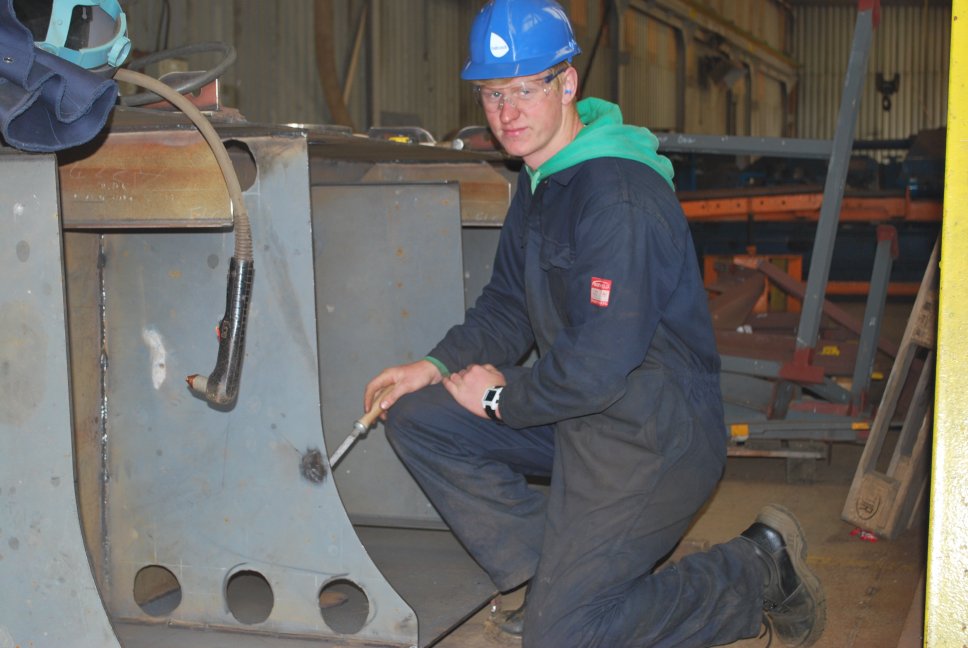
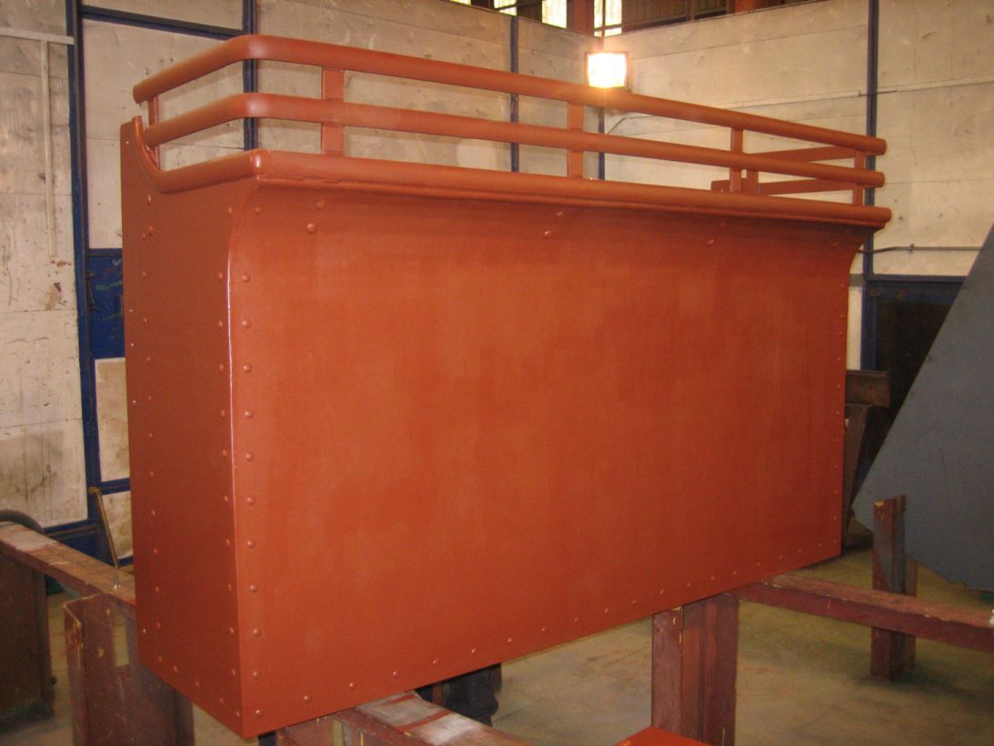
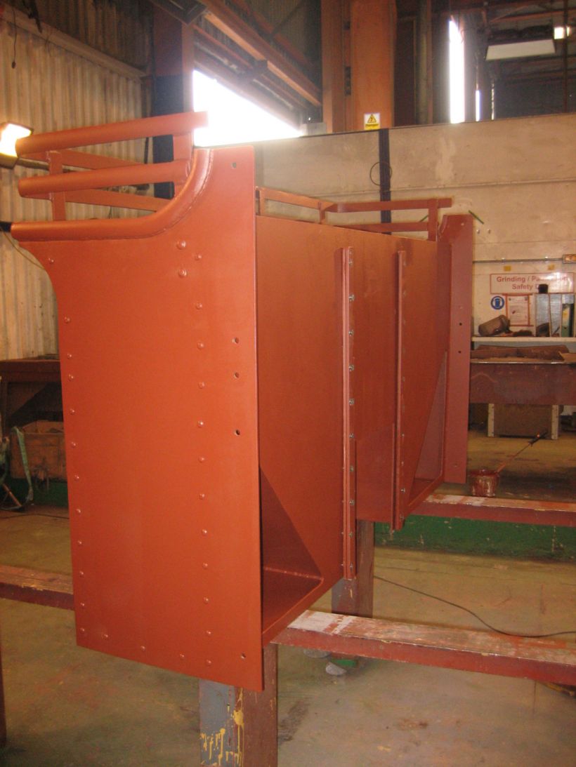
The blast stand and the spark arrestor are ready to me made and the bunker is nearing completion. The simulated riveting looks convincing.
A bit slow this month sorry about that.
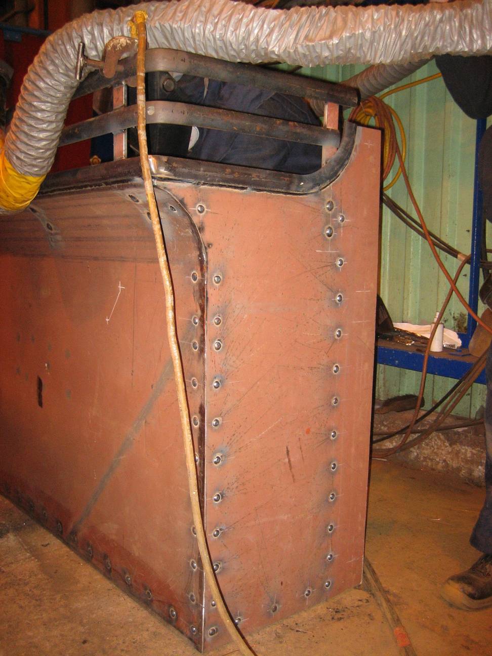 Bunker side view. |
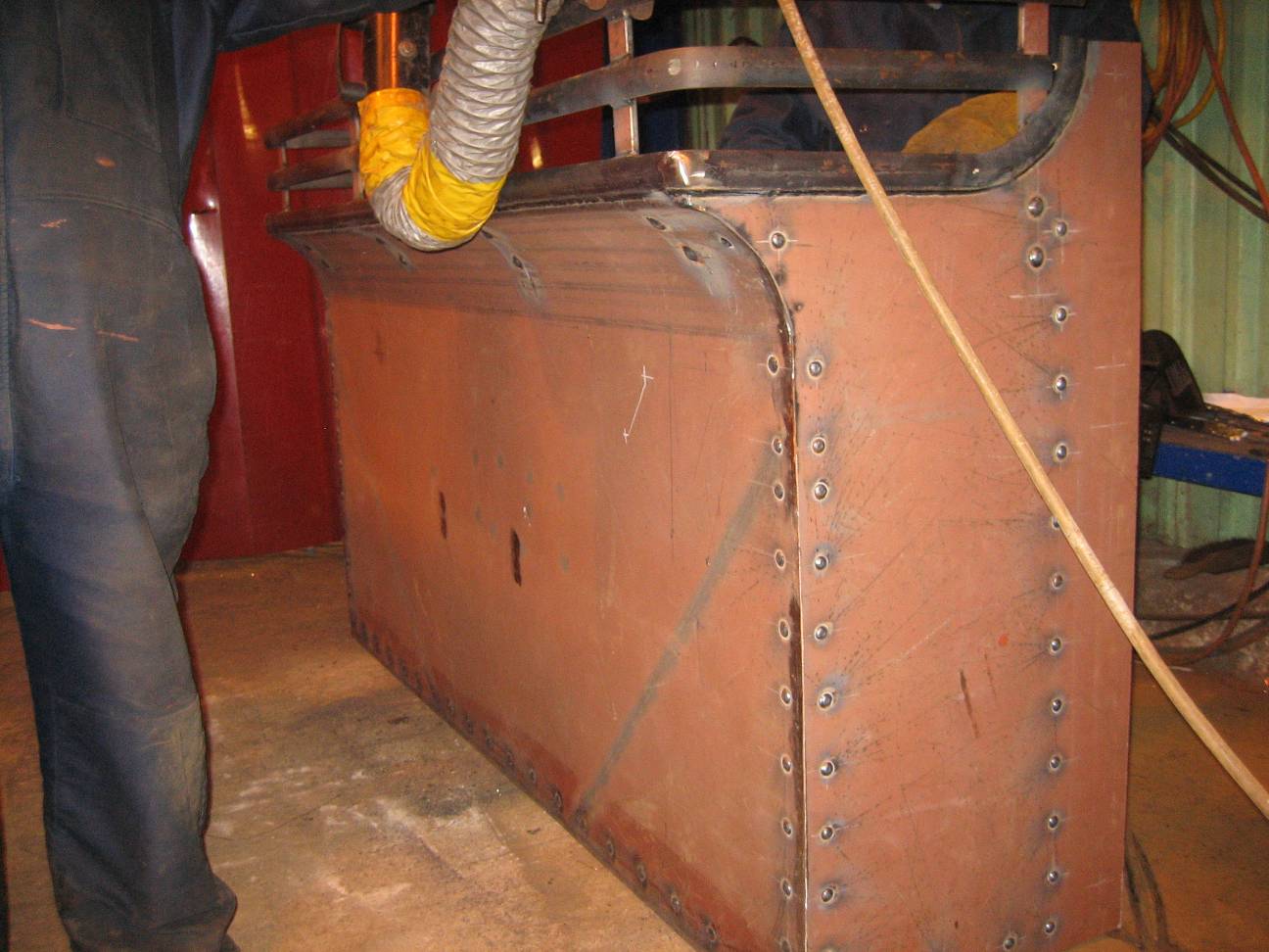 Bunker back view. |
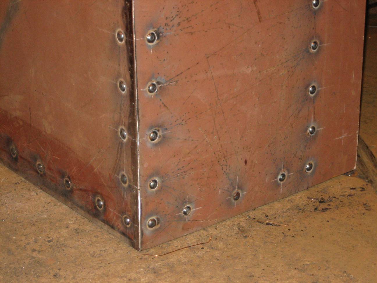 Bunker riveting detail. |
First pictures of the patterns for the cylinder covers. Really beautiful work by Brian Lloyd. It is really encouraging that these skills are still available.
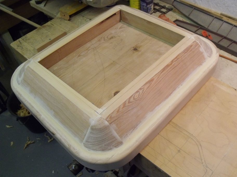 Cylinder Cover Pattern during construction. |
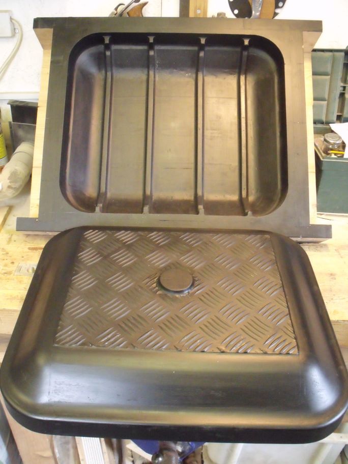 Cylinder Cover Pattern finished. |
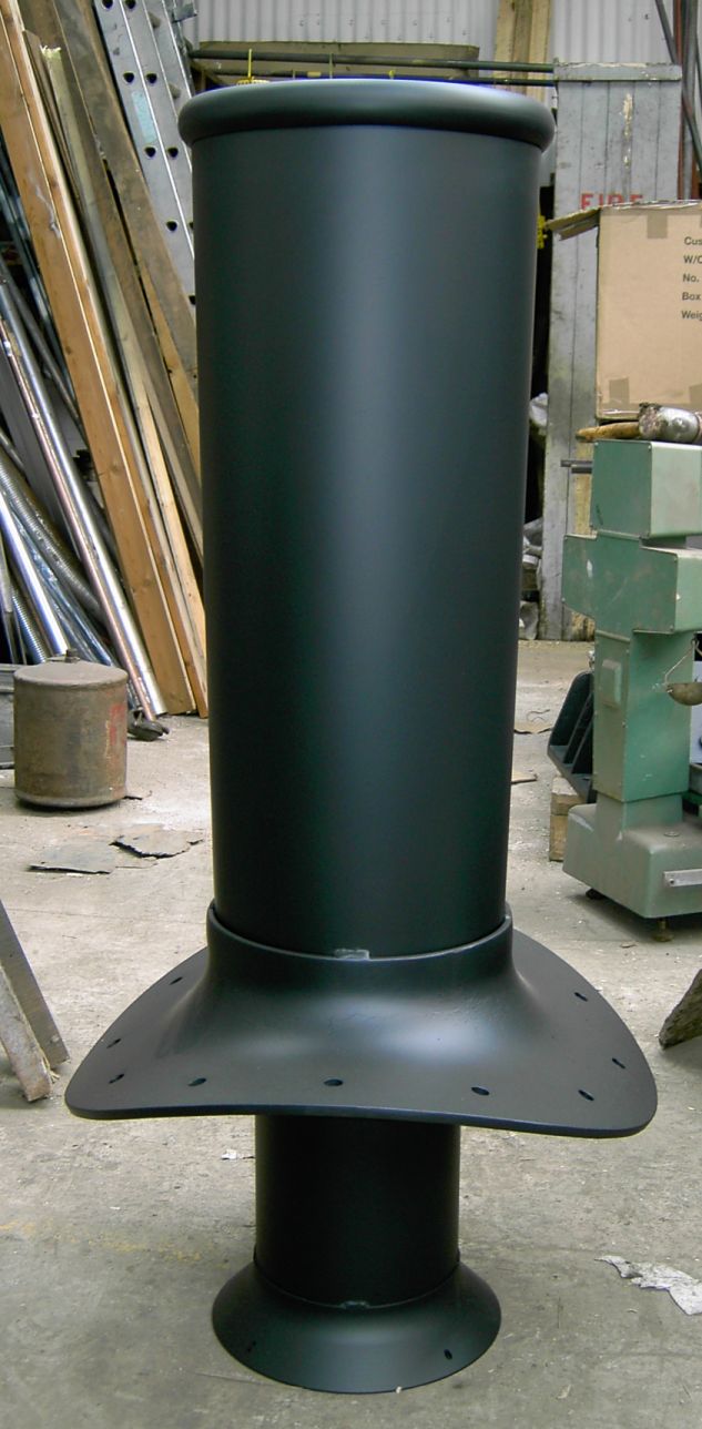 Chimney assembly. |
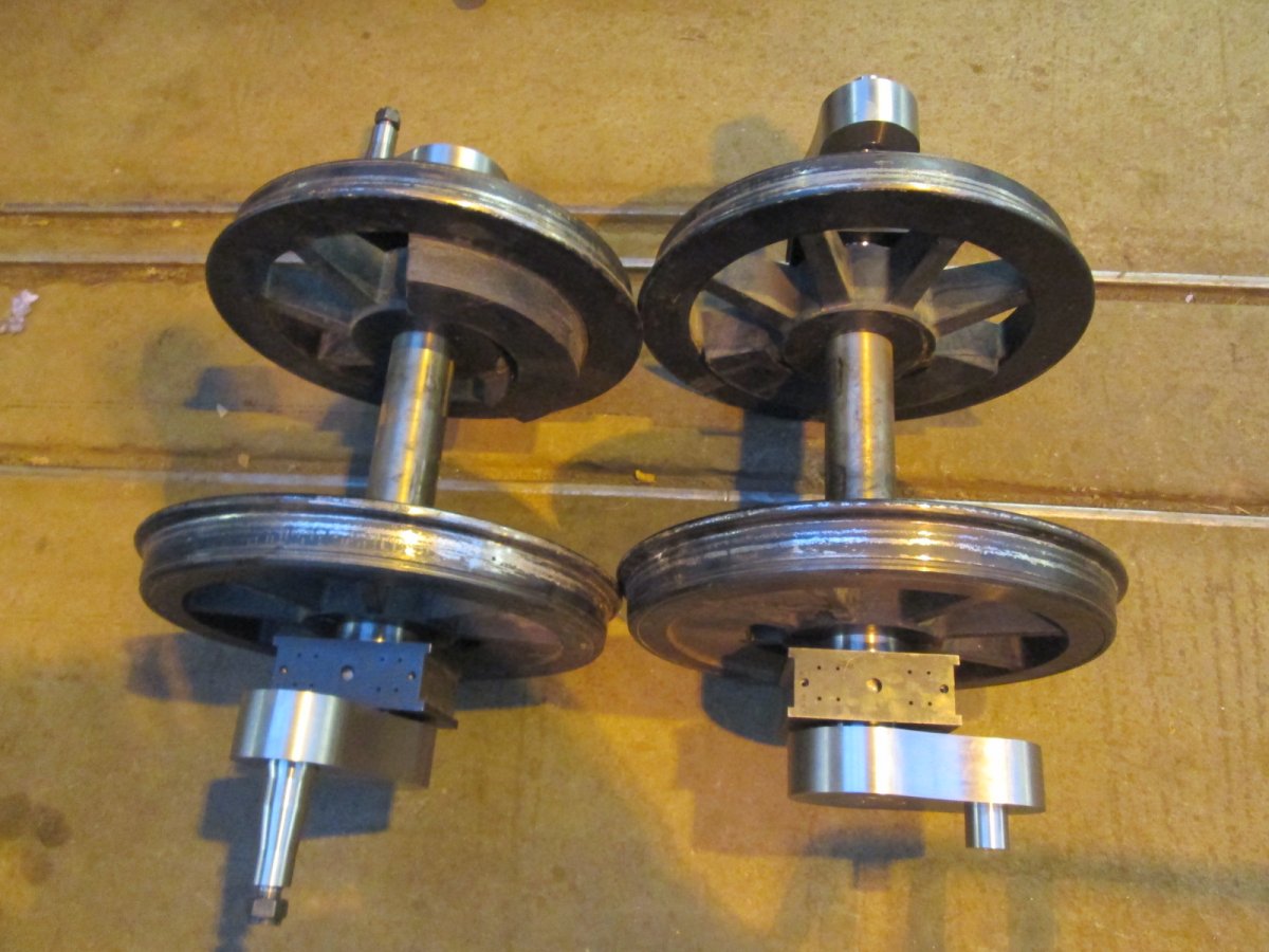
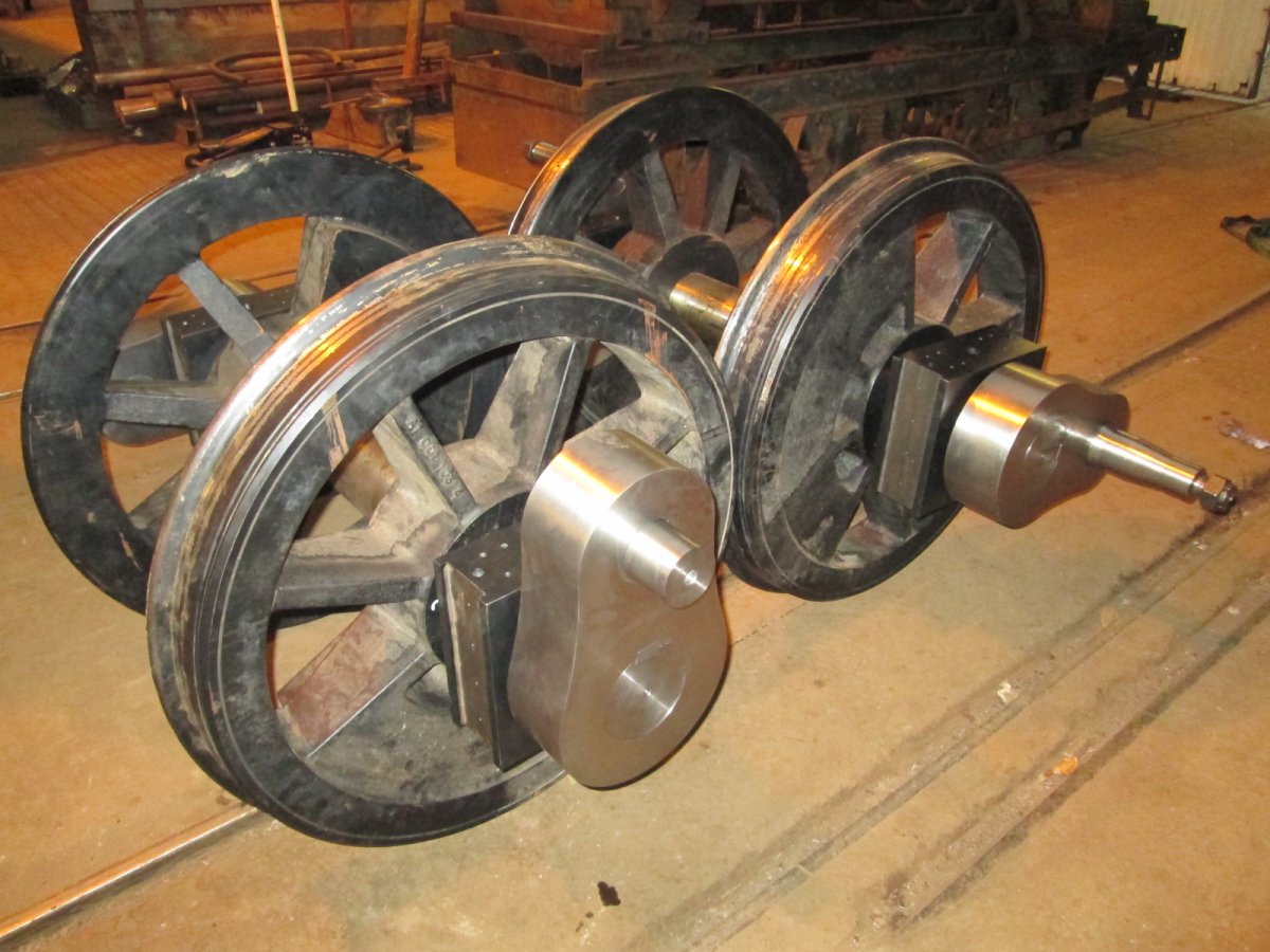
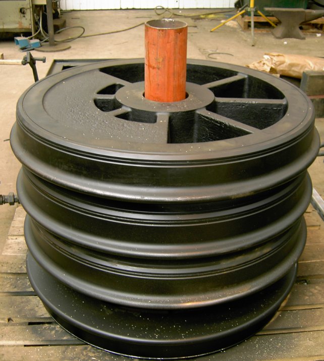 Machined driving wheels. |
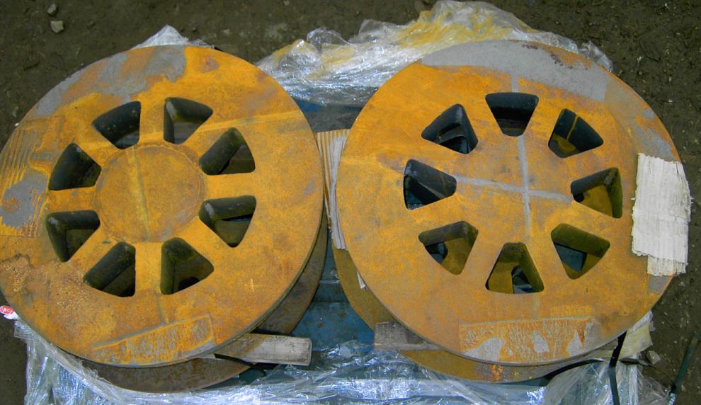 Truck wheel castings. |
 First view of the superheater and its tubes fitted to the boiler. |
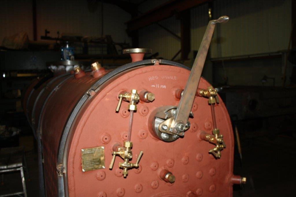 Boiler now sporting water gauges. |
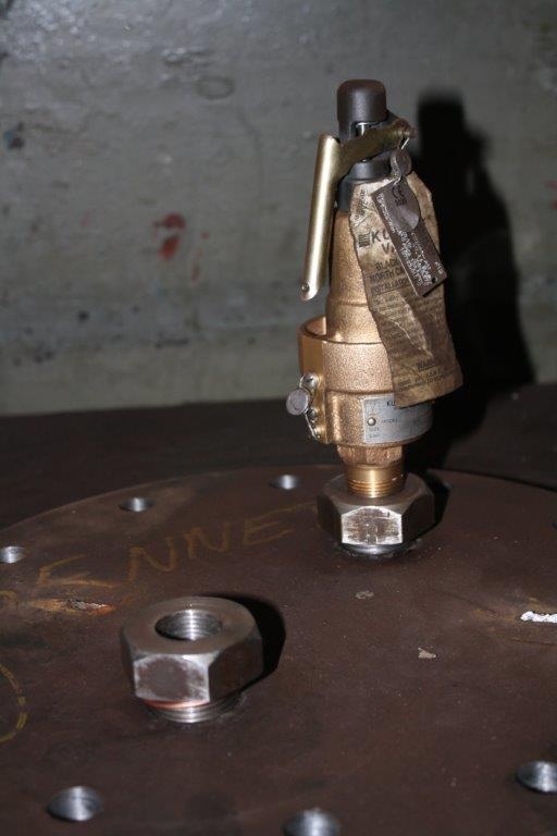 Safety valve. |
 Water Tank Team. |
 Water Tank. |
 Water Tank. |
 Fettling the tank. |
 Bunker rear view. |
 Bunker back view. |
 Fire Door Closed. |
 Fire Door Open. |
 Water tanks finished and undercoated. |
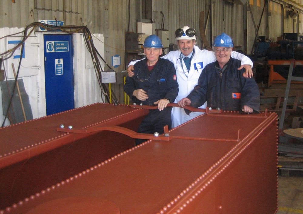 The team responsible. The chap in the middle is Michael Guppy who has made such a great job possible. |
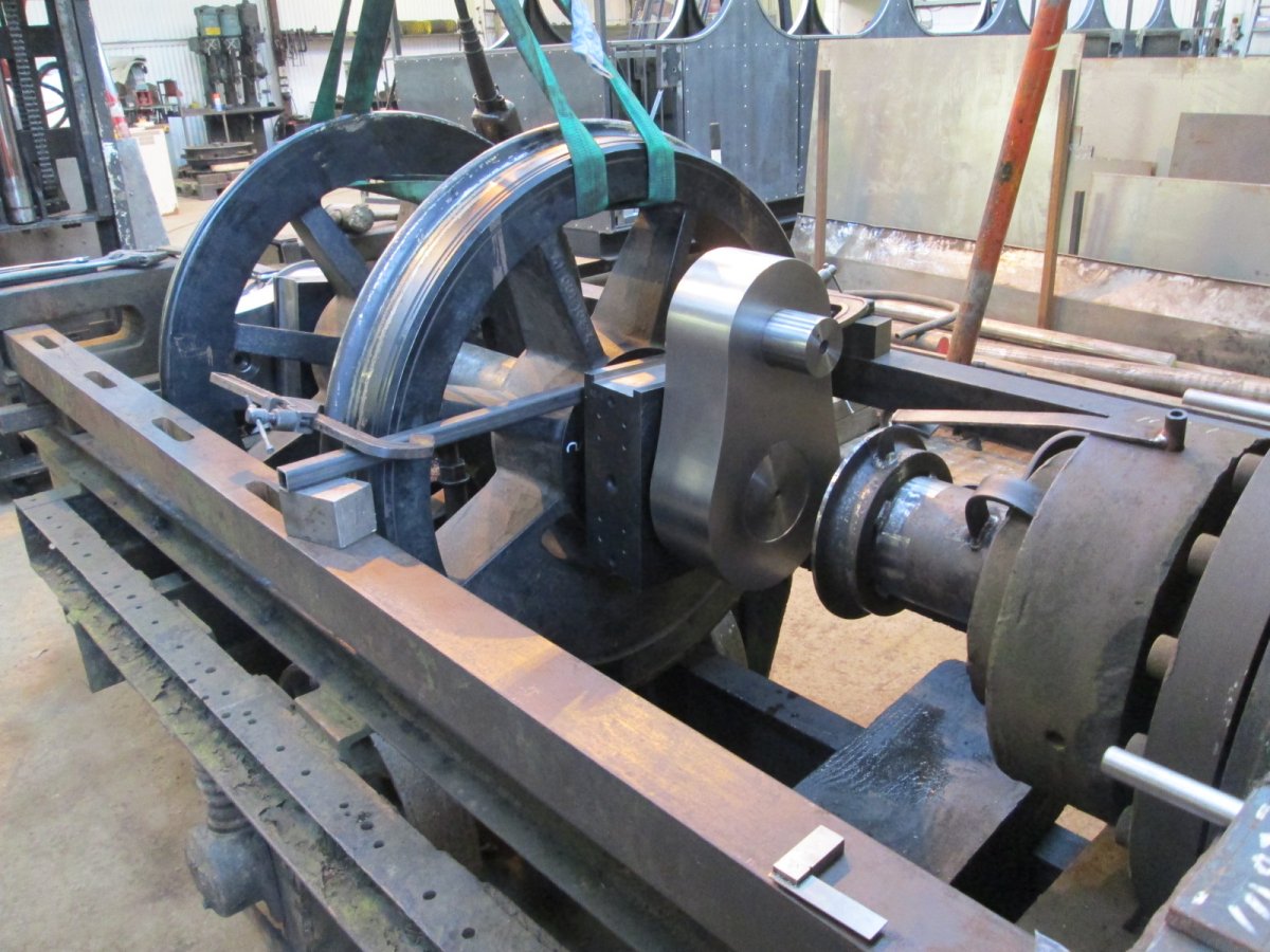
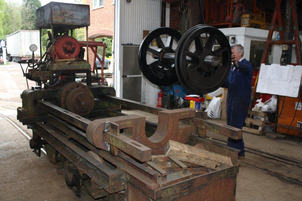 The machine used to press on the wheels. Quite different from what I expected. |
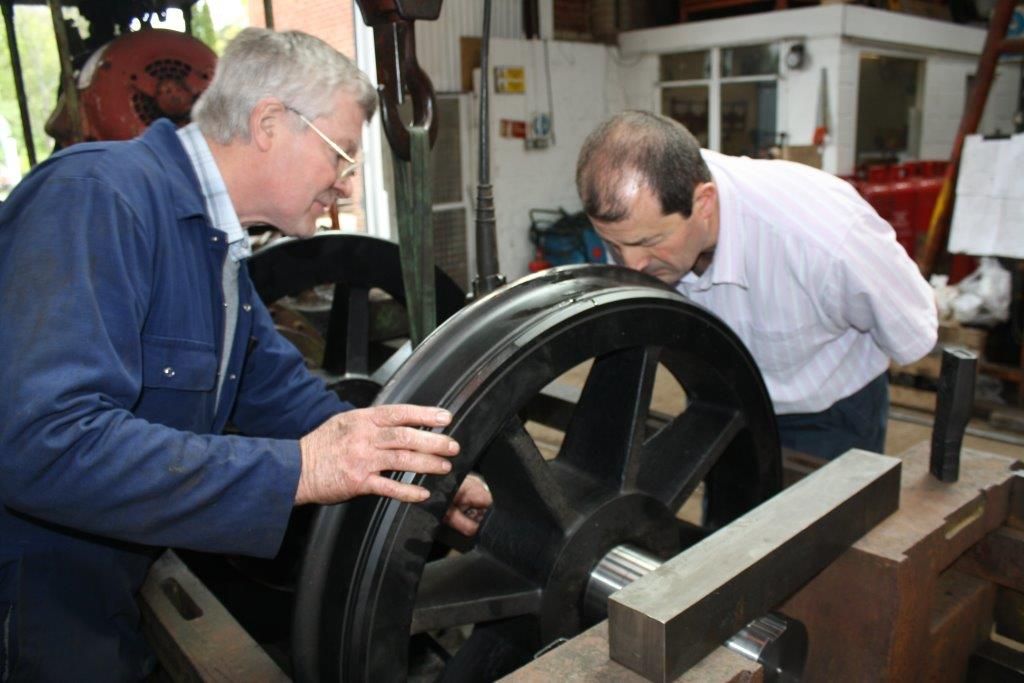 Patrick and Phil checking the job. |
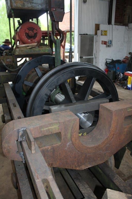 The axle press in action. |
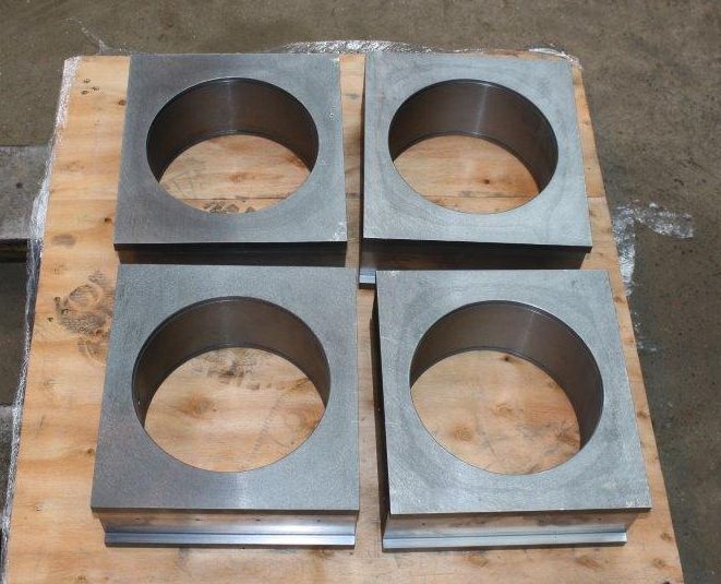 Axle boxes machined and waiting to be assembled onto the axles. |
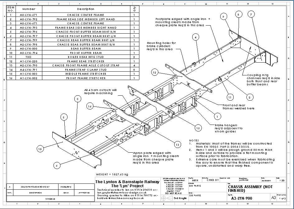 Frame assembly drawing (not finished). click on drawing to download the 3 sheet pdf. |
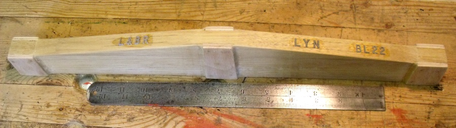 The finished woodwork before painting. |
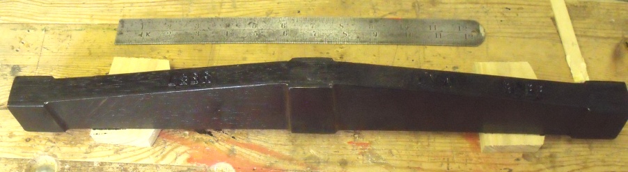 The finished pattern ready for casting. |
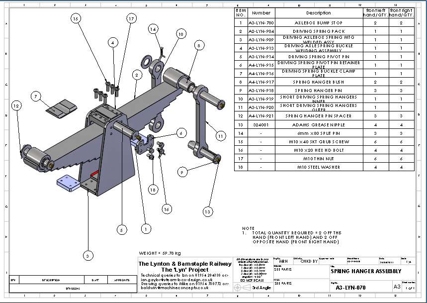 spring mounting assembly drawing (not finished). click on drawing to download the drawing pdf. |
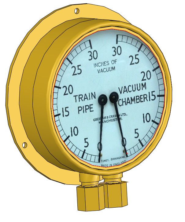 Modelled Vacuum Gauge. |
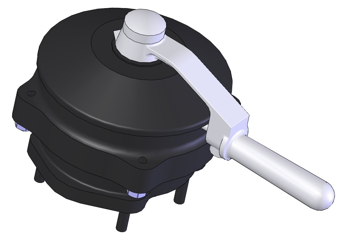 Modelled Drivers Steam Brake. |
 Modelled Whistle. |
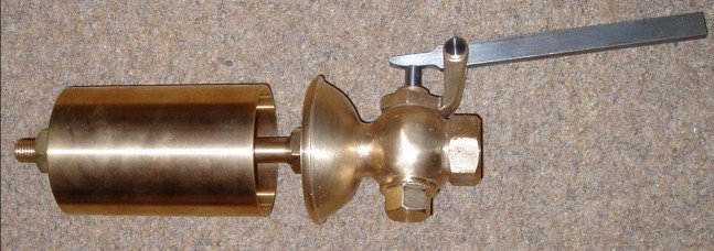
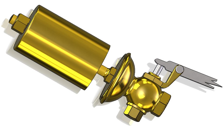
 Steam Brake Displacement Lubricator. |
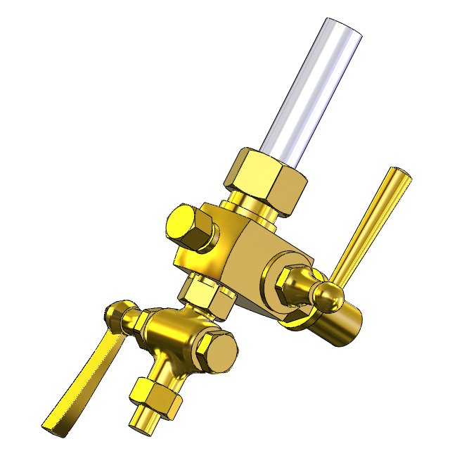 Modelled Gauge frame (bottom left shown). |
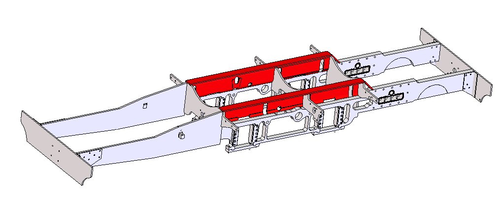 Stiffened Frame Assembly. |
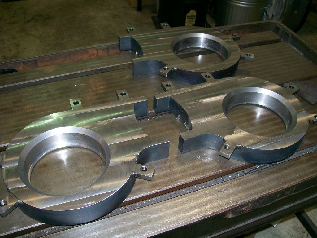
 cylinder end flanges showing the CNC machining. |
 cylinders machined ready for assembly. |
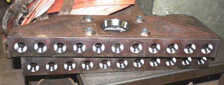
 Steam Transfer Port Profiles. |
 Steam Chest end Plates. |
 Main Cylinder and Steam Chest. |
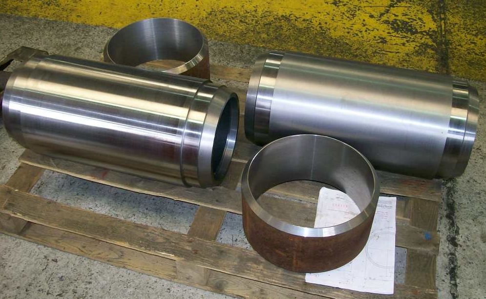
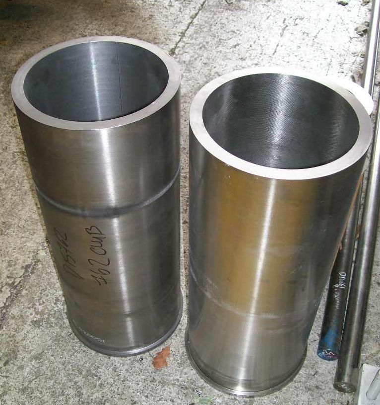 Cylinder Liners Proof Machined. |
 Exhaust Guide Parts. |
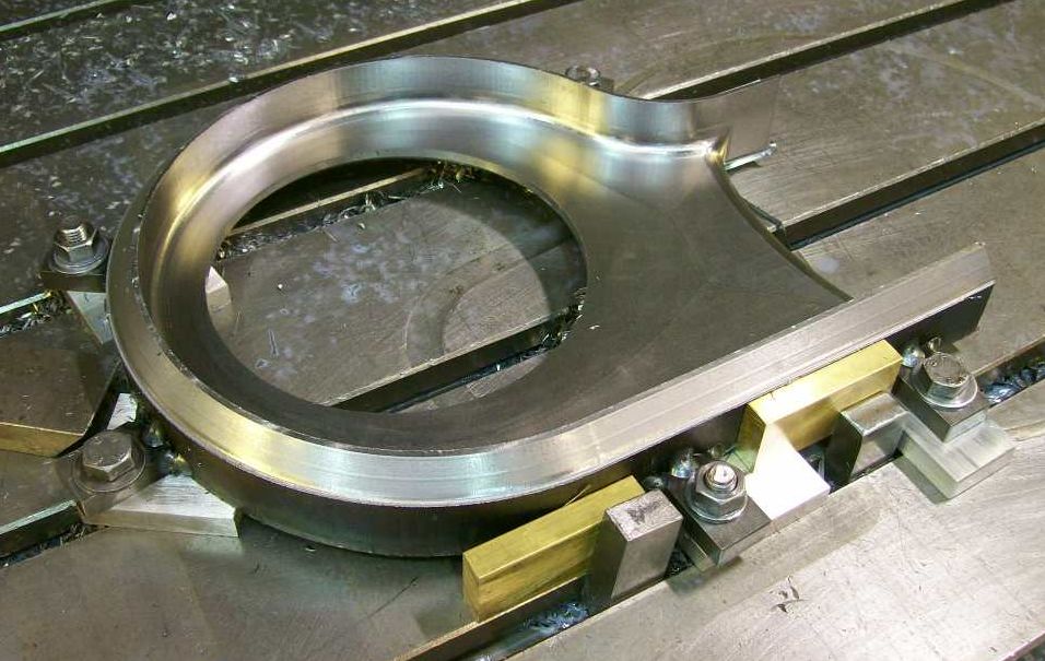
 Blast Stand all welded up. |
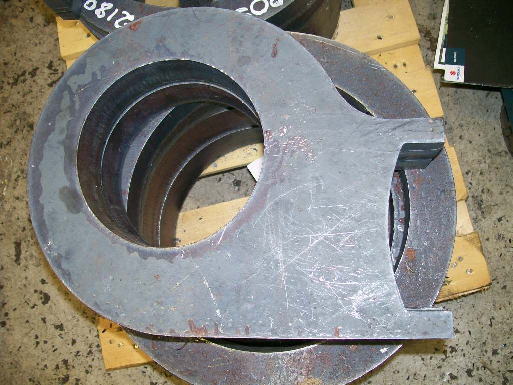
 Blast stand part. |
 Blast stand part. |
 Blast stand part. |
 Front Pony Truck. |
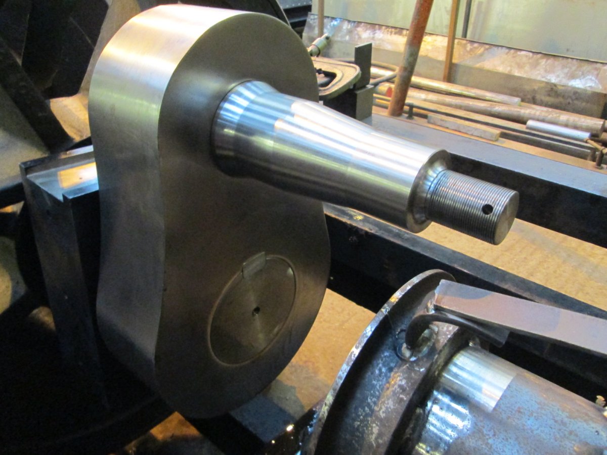
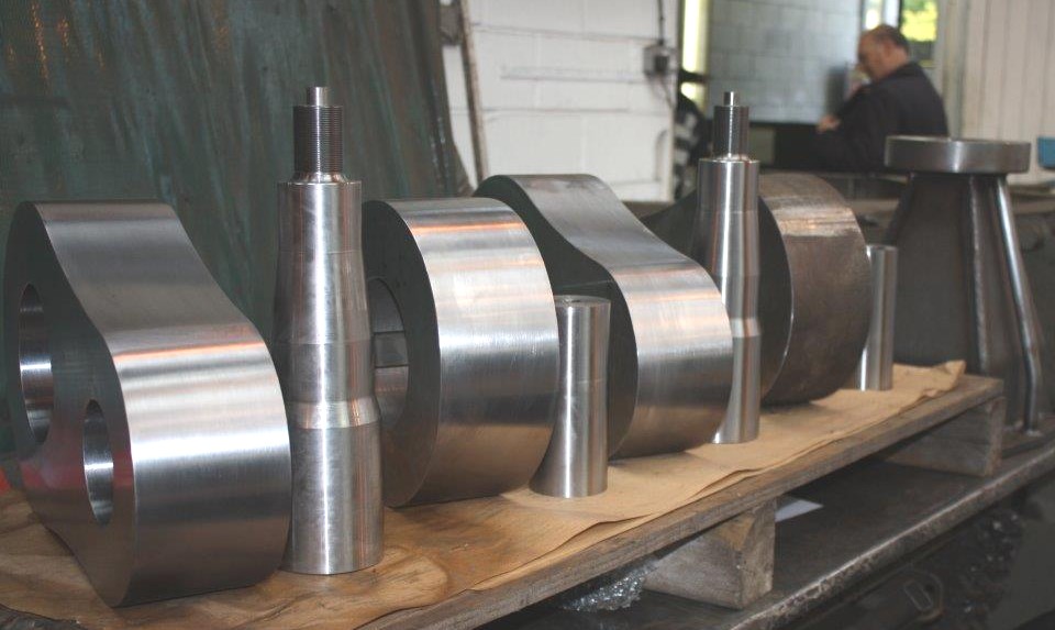 Cranks and crank pins. |
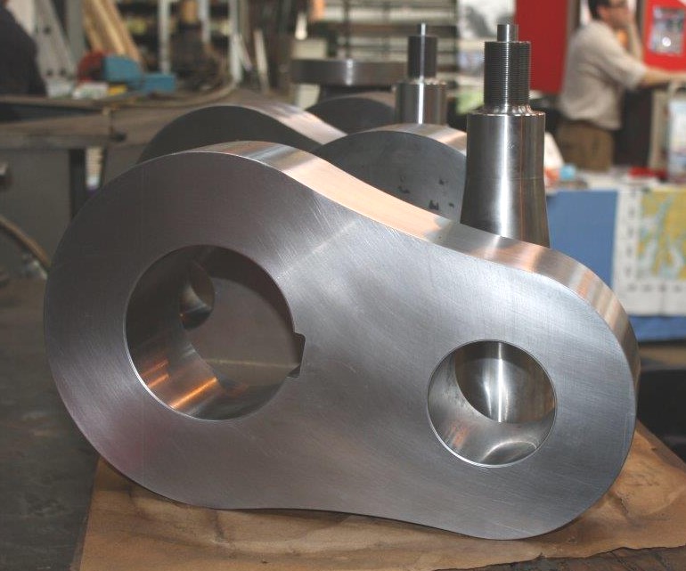 Crank. |
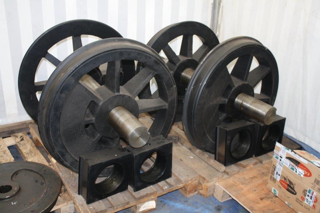 Main wheel Sets. |
 Fire Bars ready to use. |
 Valve conrods part assembled. |
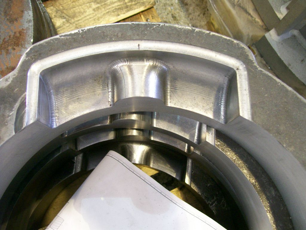
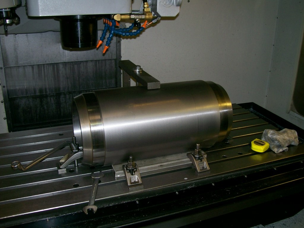
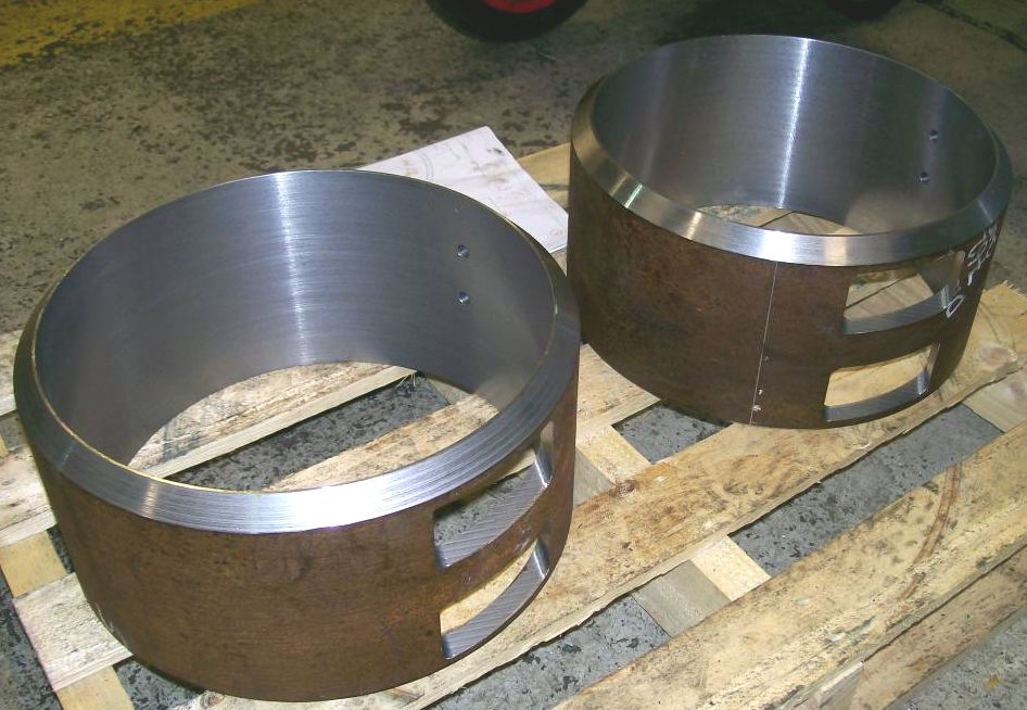
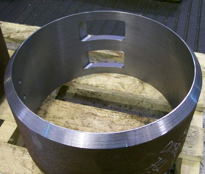
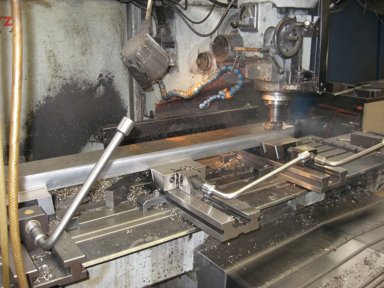
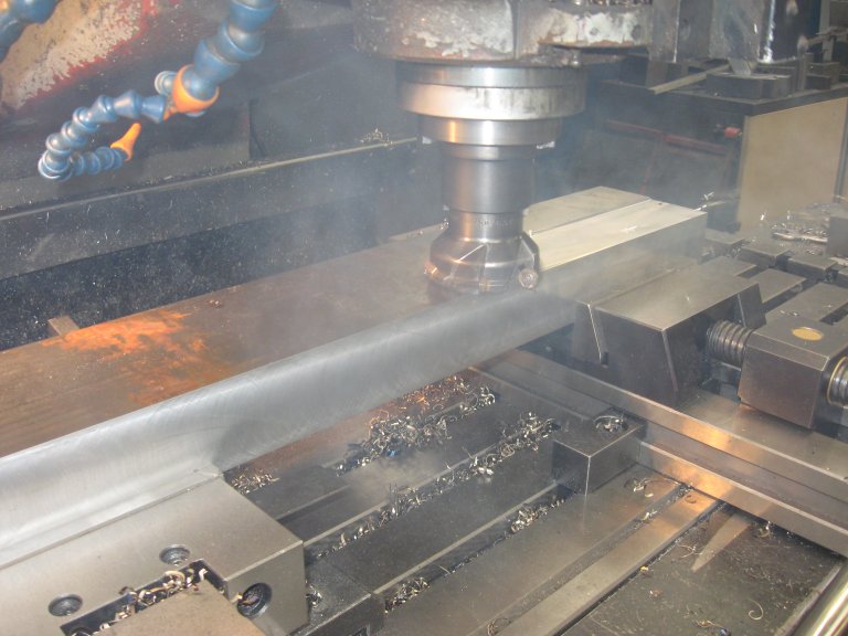
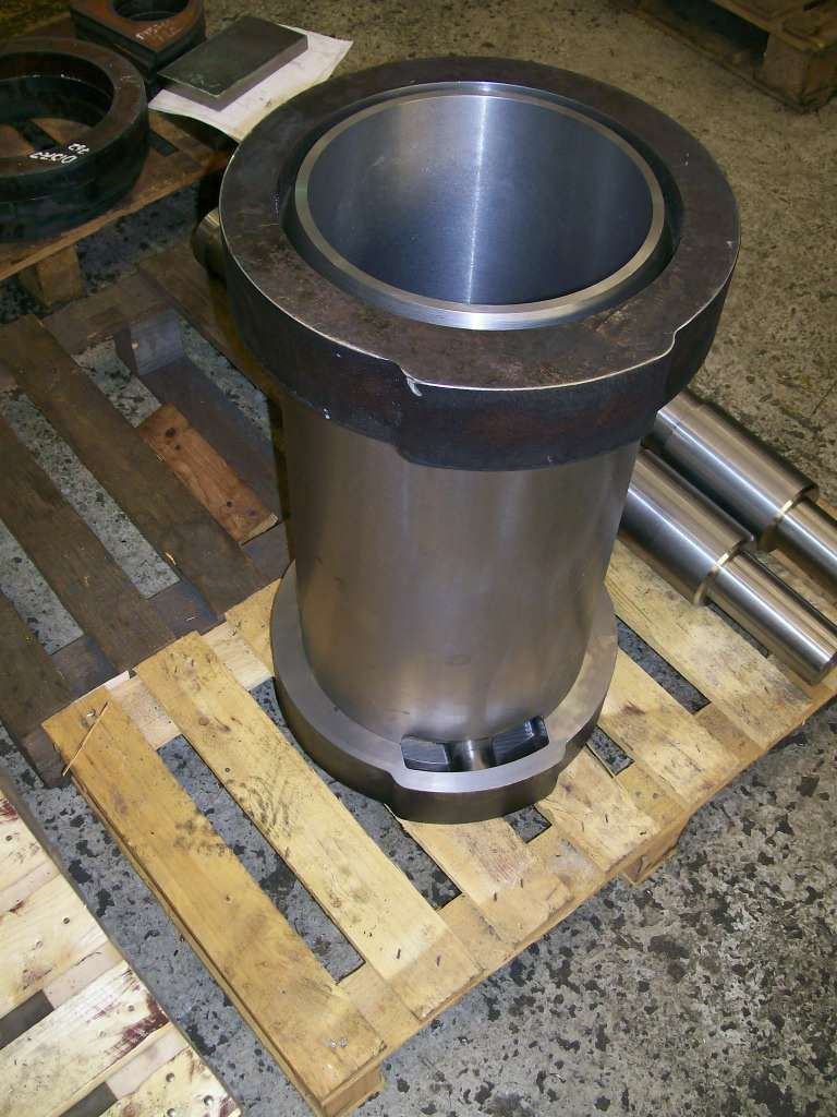
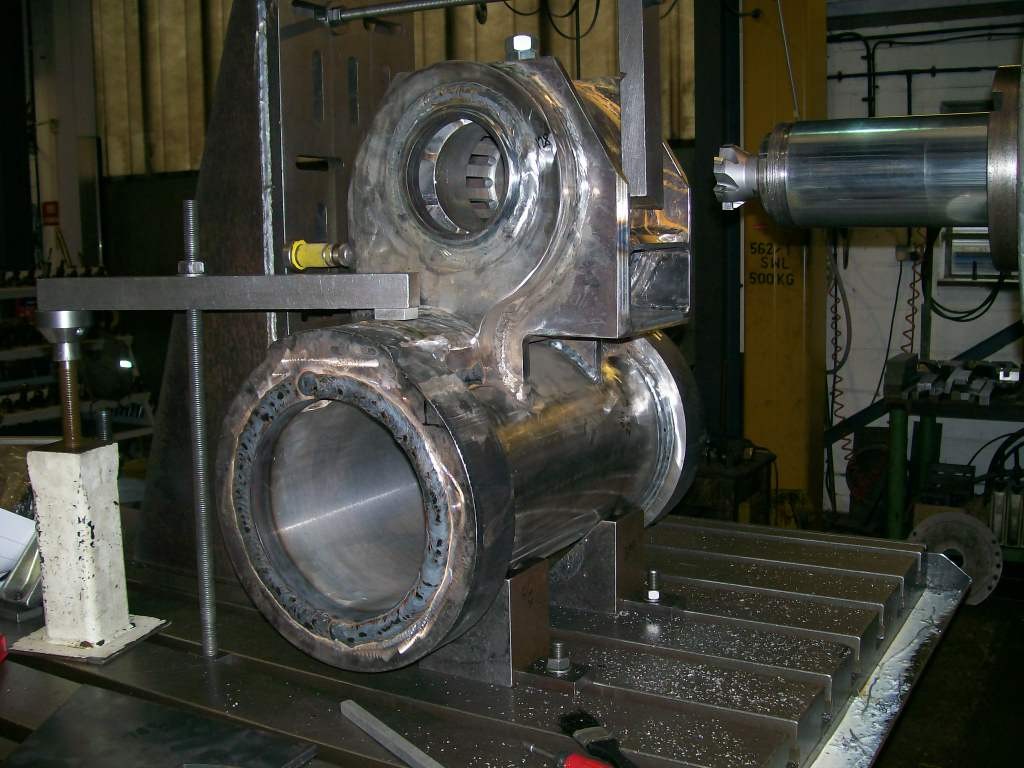
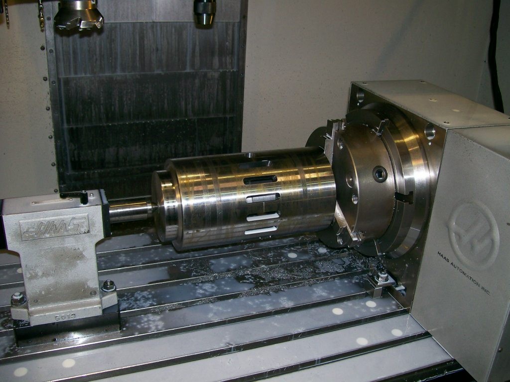 Machine the valve cylinder. |
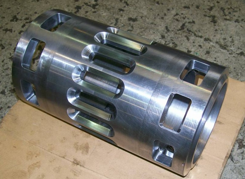 Valve Cylinder machined. |
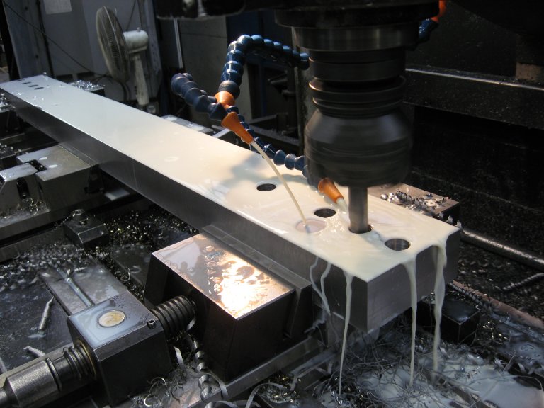
 Steam Cylinder set up for port milling. |
 Gradable steam brake. |
 Valve chest top cover casting. |
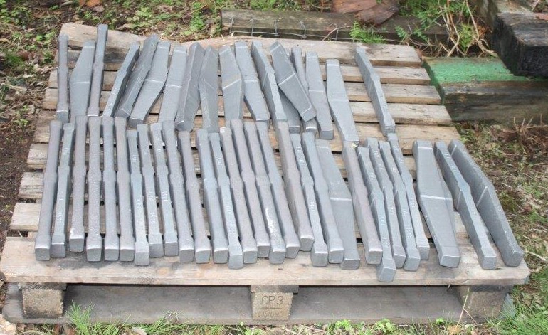
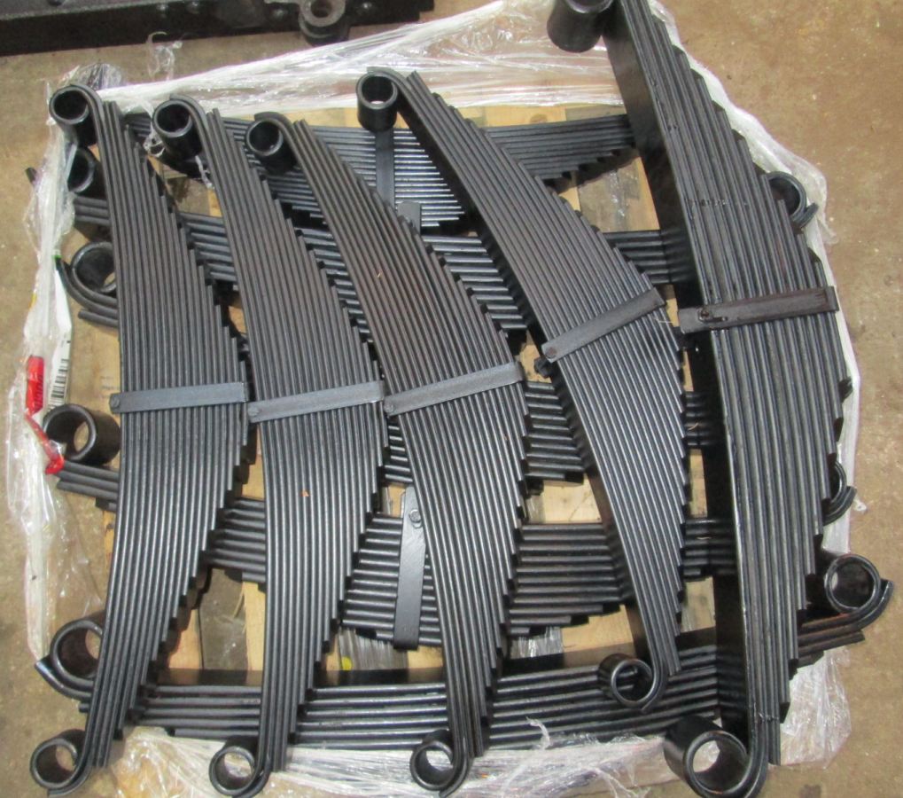 Springs. |
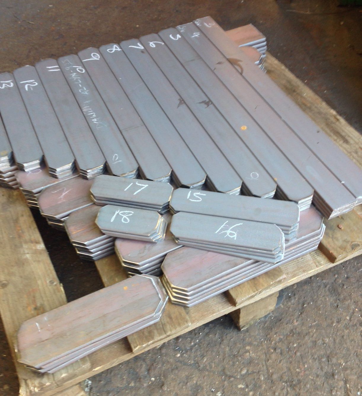 Spring Materials. |
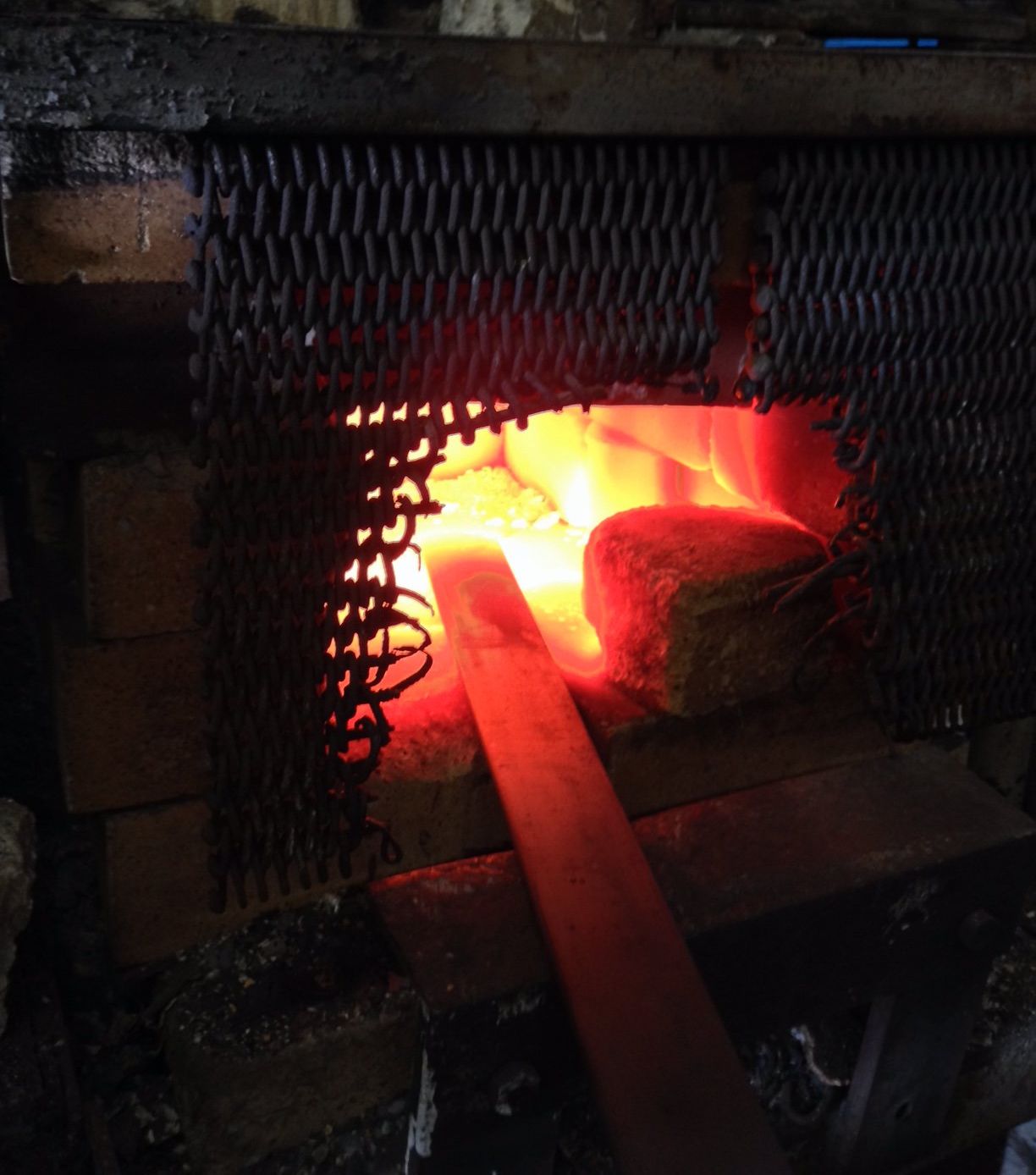 Heating the spring. |
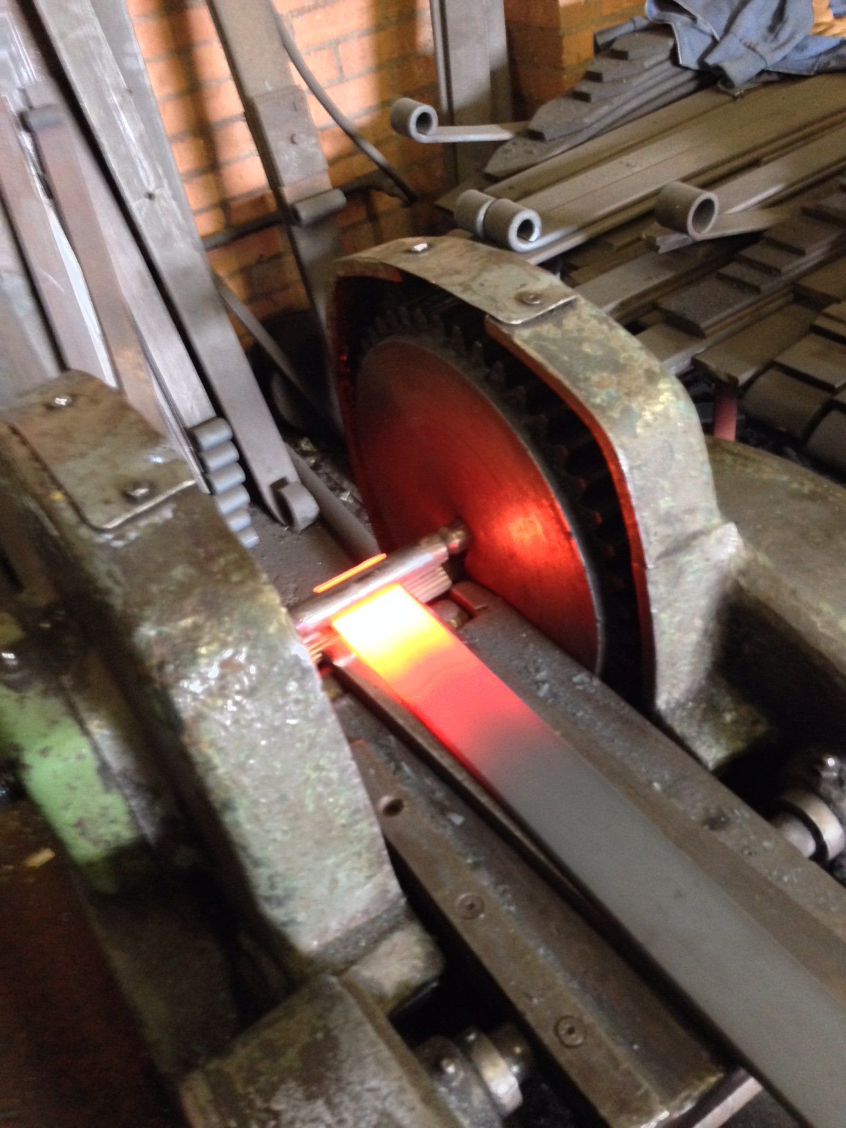 End forming first bend. |
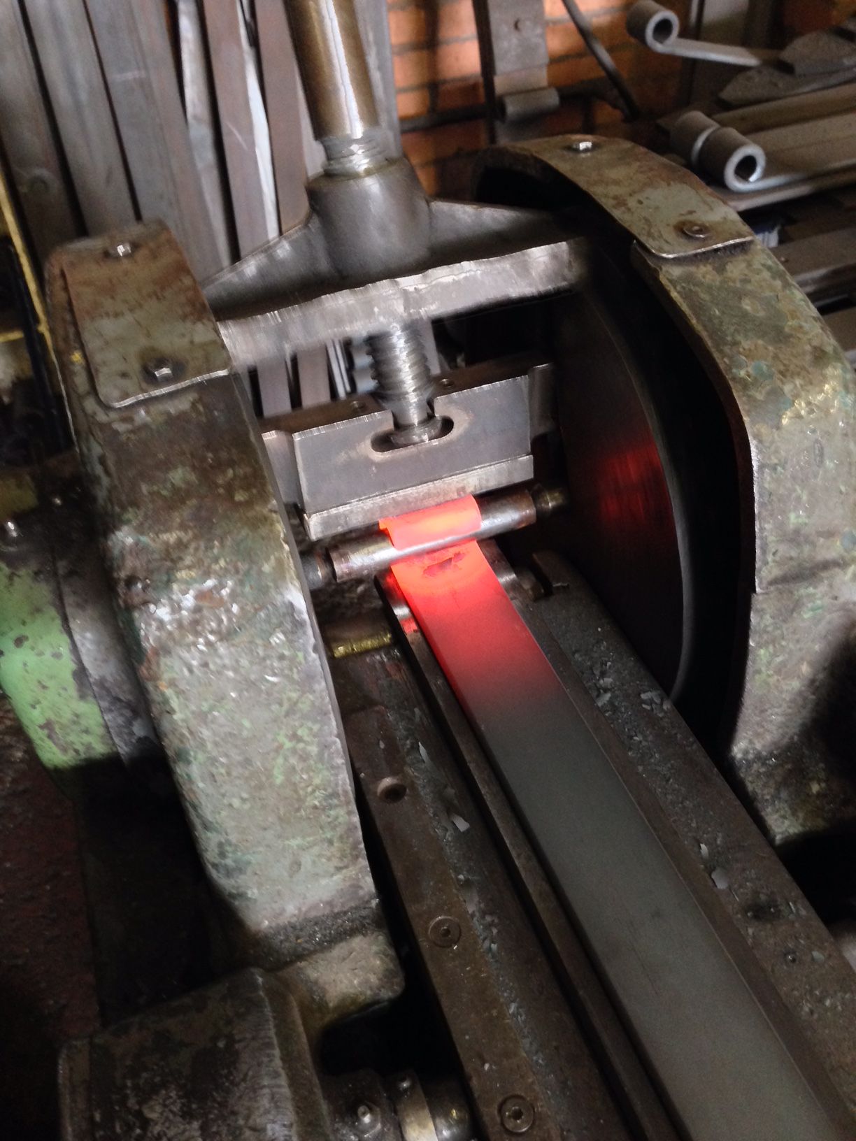 Finishing the ends. |
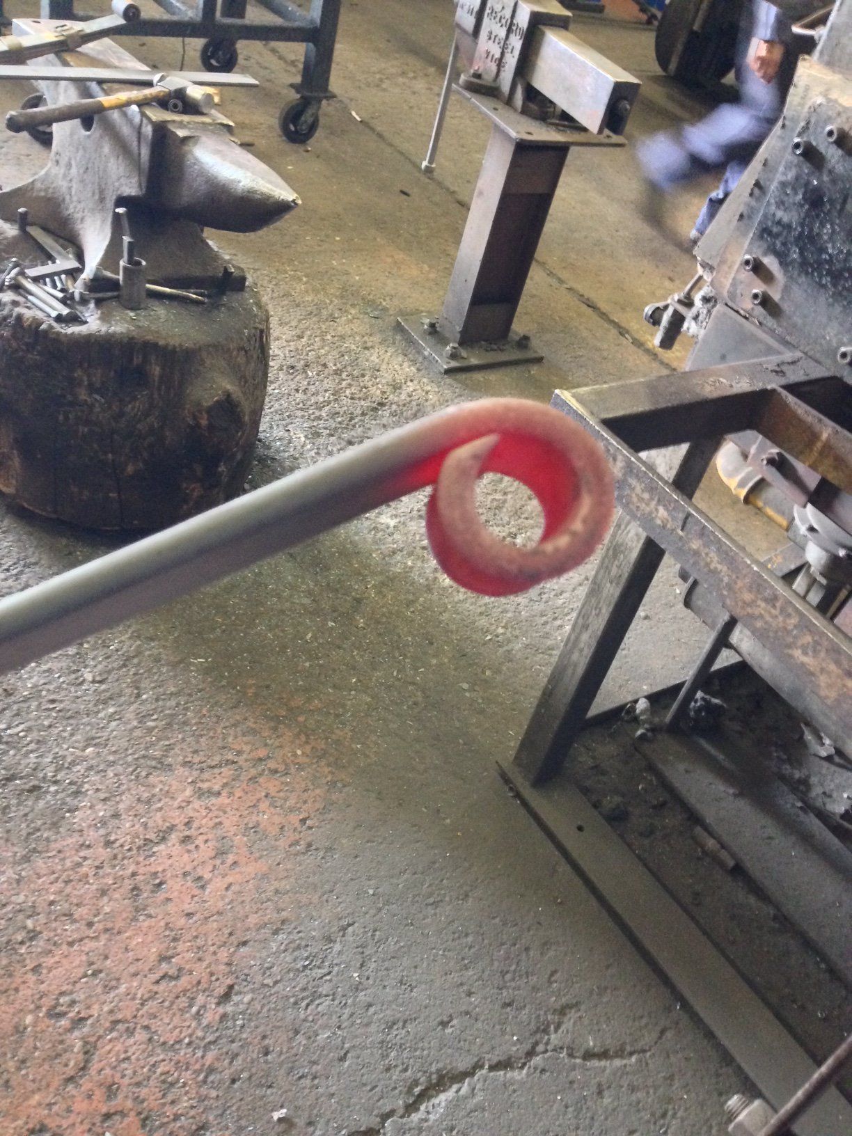 Finished end of spring leaf. |
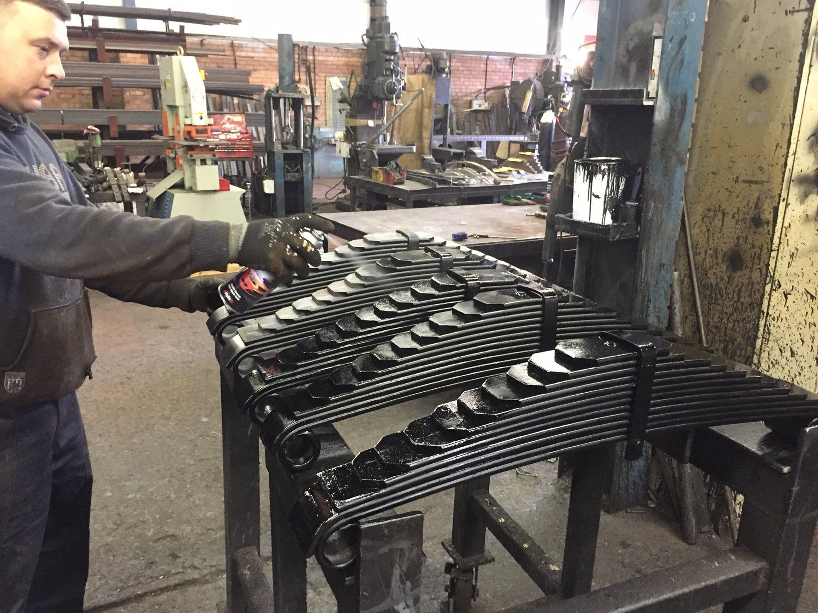 Spraying the springs. |
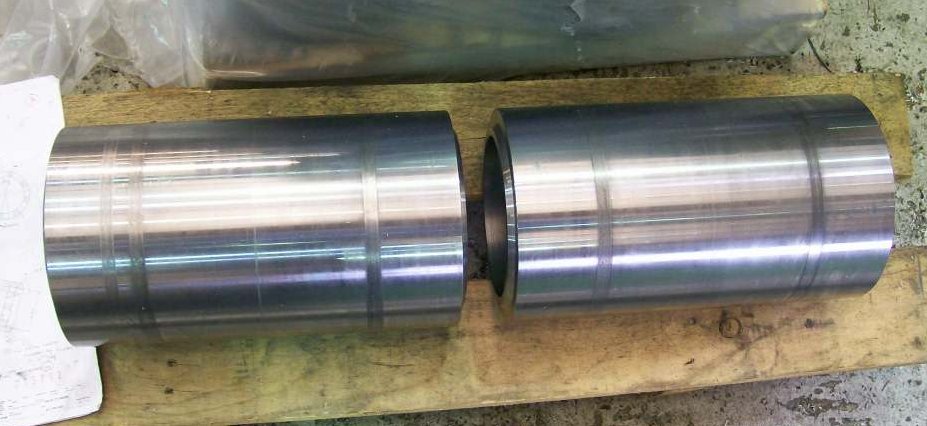
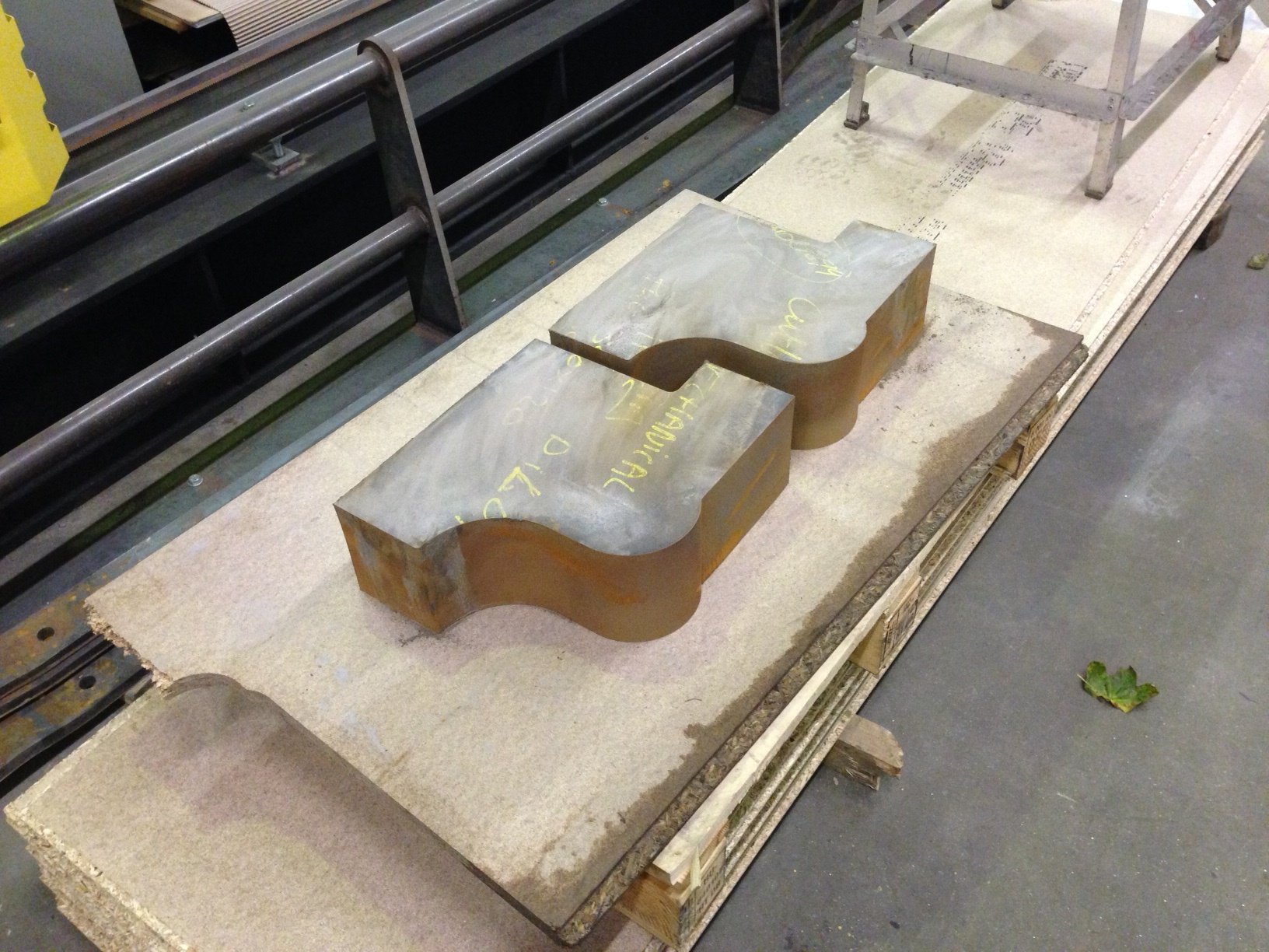
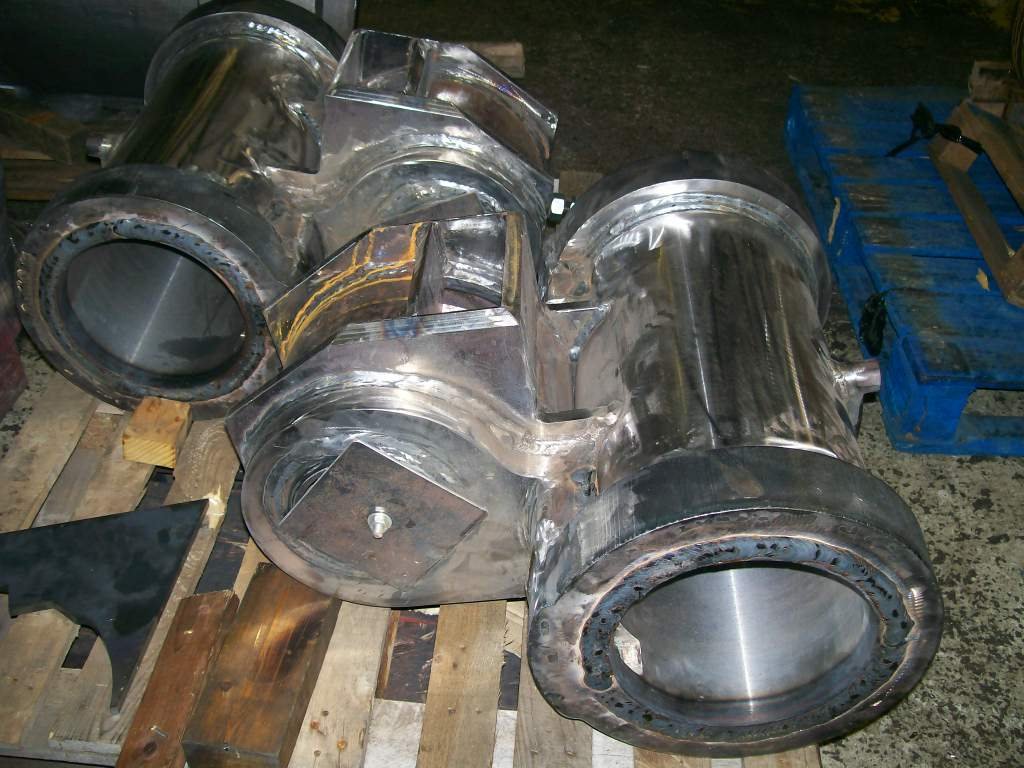
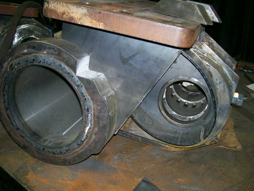
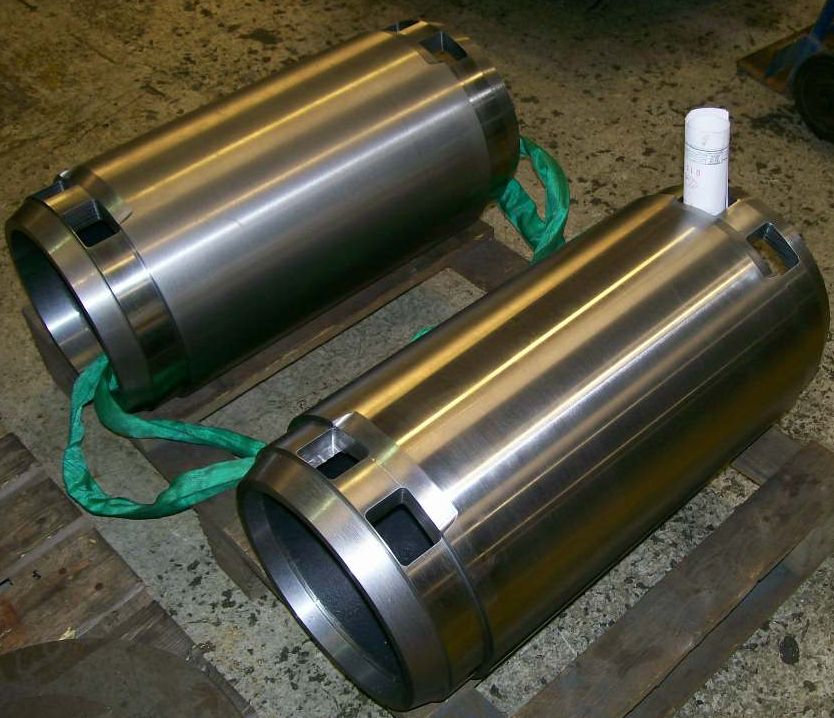 The 2 machined cylinder bodies. |
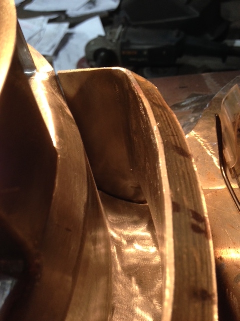
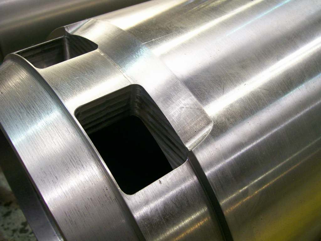 Steam cylinder port detail. |
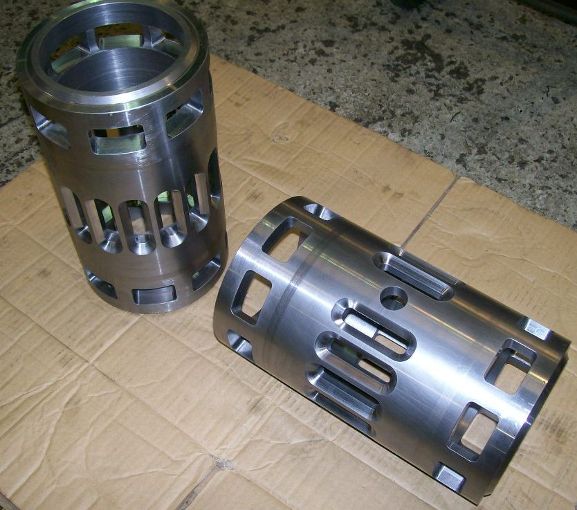 The completed valve cylinders. |
 Finished steam chests. |
 Steam chest detail. |
 Liner Guide and instrumentation boss. |
 Valve conrod fabrication. |
 Steam transfer ports initial machining. |
 Steam transfer ports stage 2 machining. |
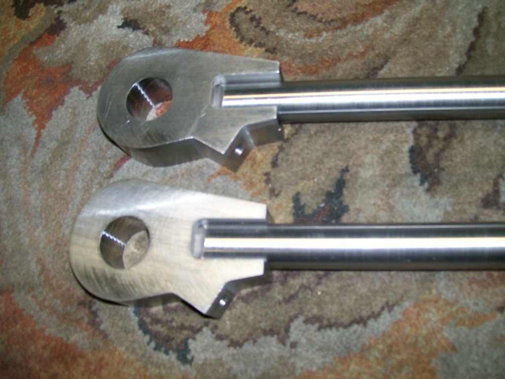
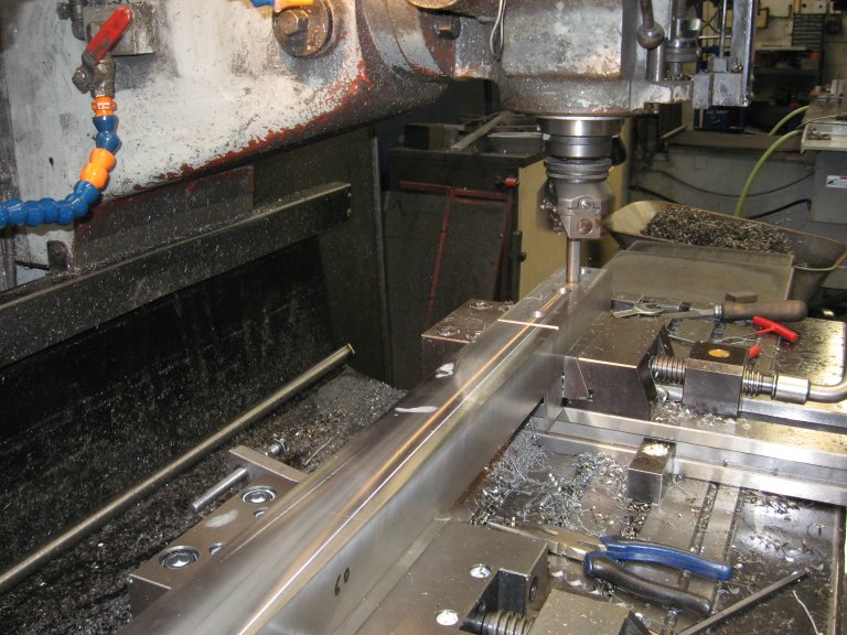 Crosshead bottom slide bar Machining. |
 Crosshead bottom slide bars ready for heat treatment. |
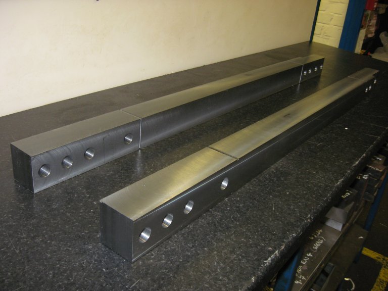
 Crosshead Top Slide Bar Machining. |
 Crosshead Top Slide Bar Roughing out. |
 Crosshead Top Slide Bar Machining. |
 Steam Chest Fabrication. |
 Steam Chest Fabrication. |
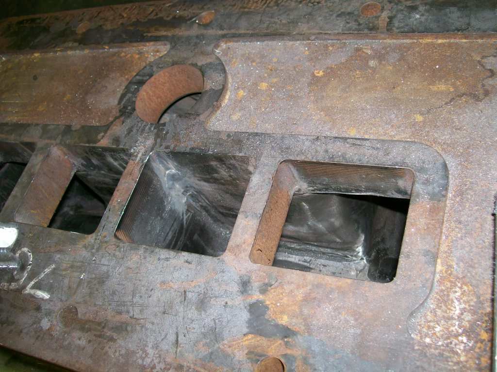
 Steam Transfer Ports ready for Assembly. |
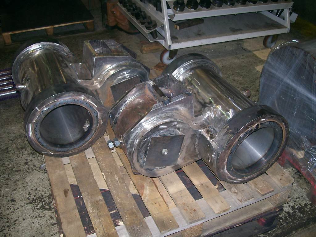
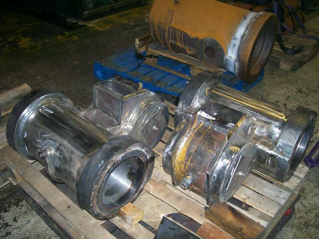
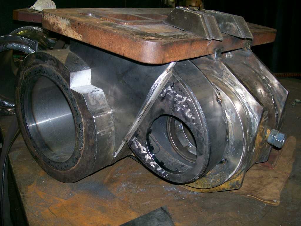
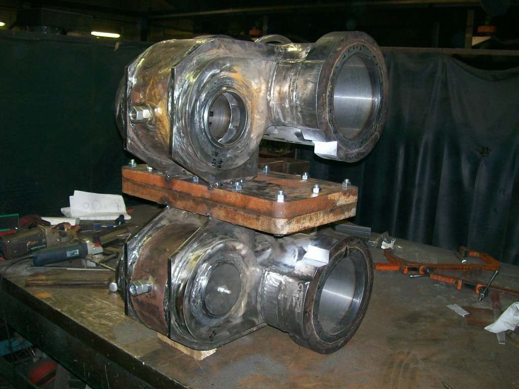
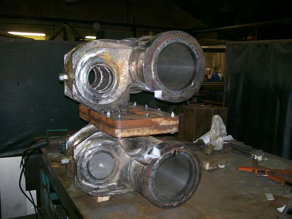
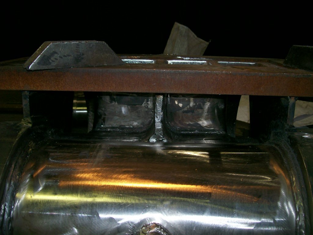
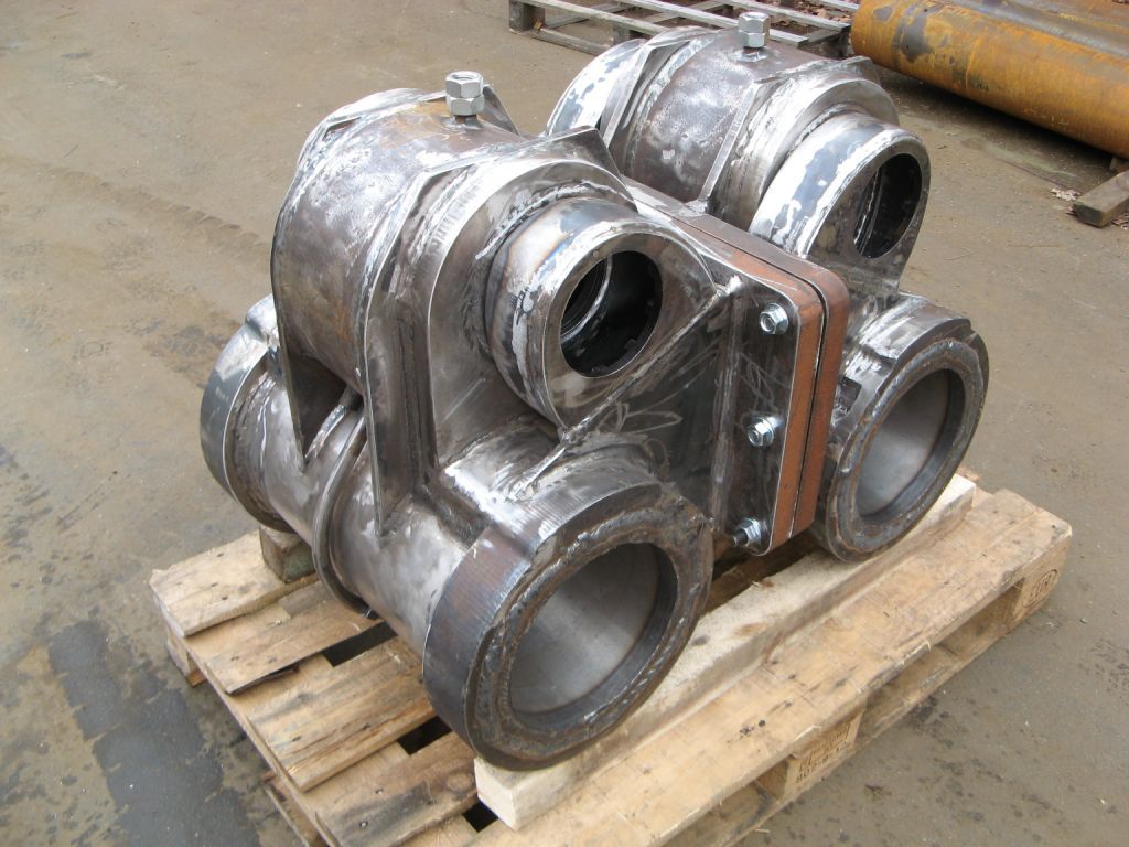
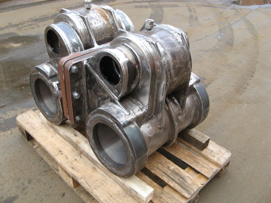
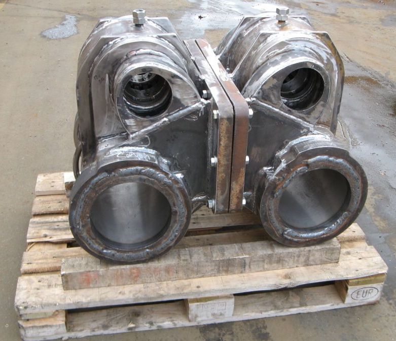
 Cylinder & Steam Chest. |
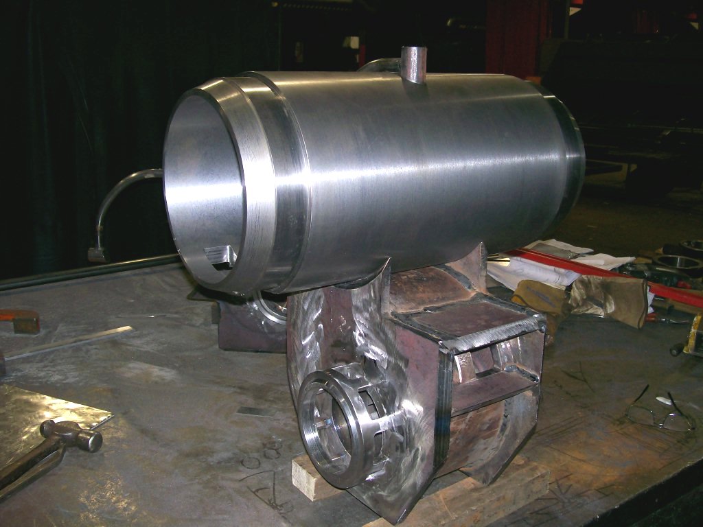 Cylinder & Steam Chest. |
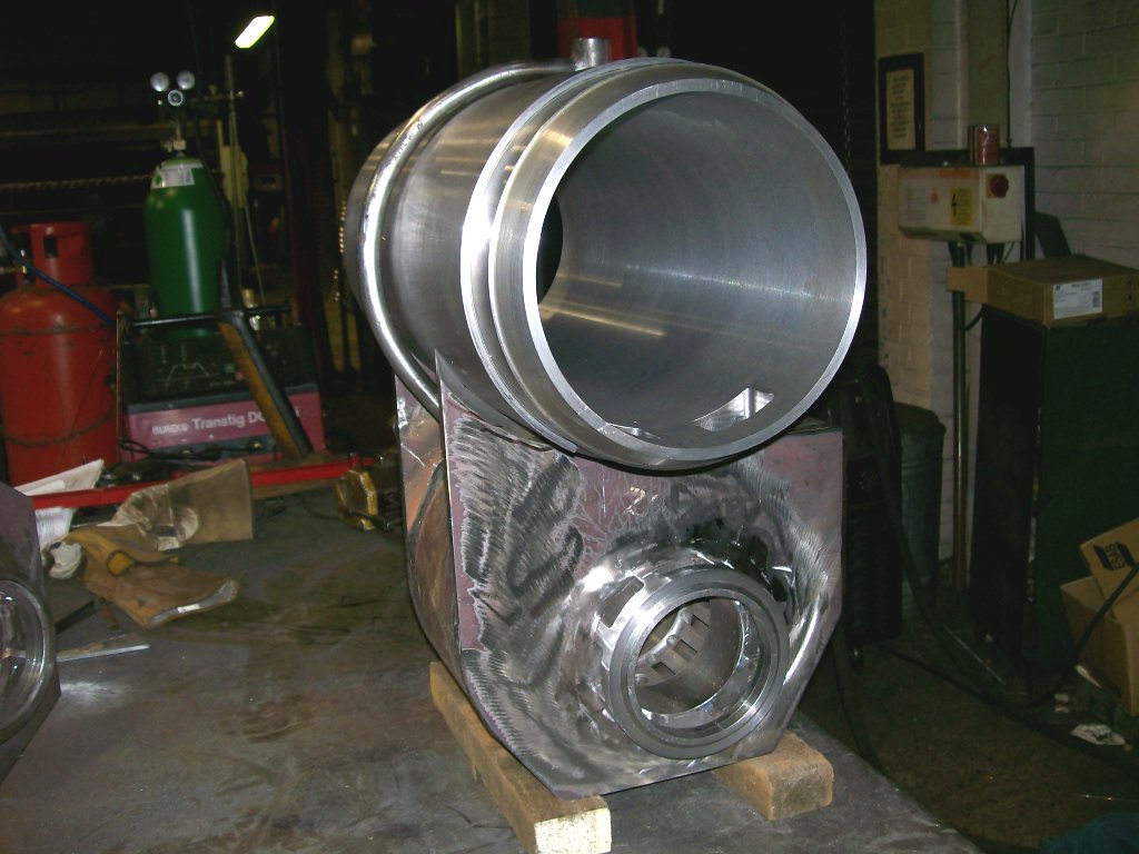 Cylinder & Steam Chest. |
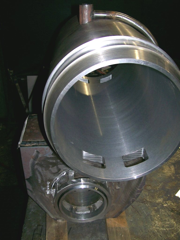 Cylinder & Steam Chest. |
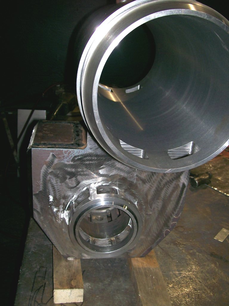 Cylinder & Steam Chest. |
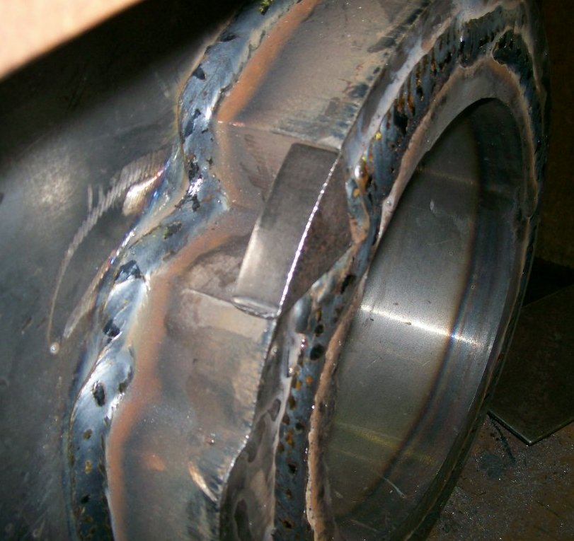
 Cylinder with End Flange. |
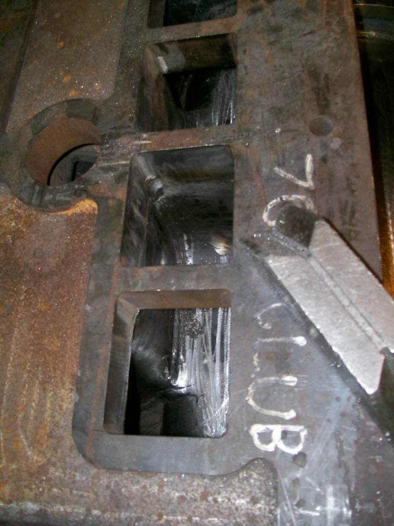
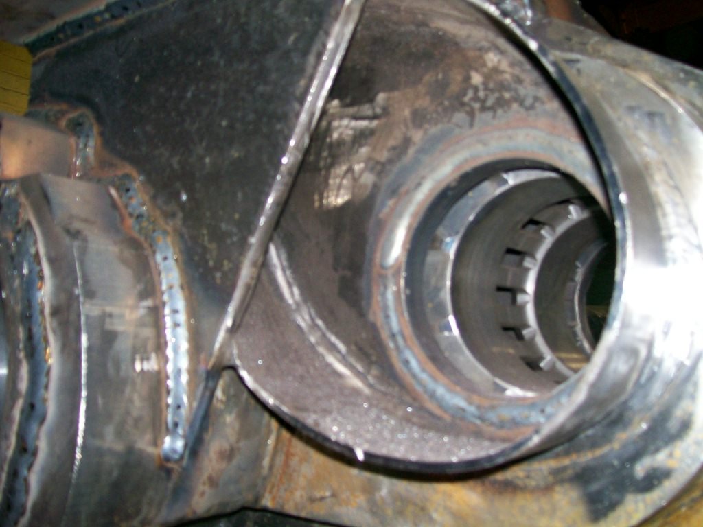
 Steam transfer port welded in position. |
 Steam transfer port showing the internal corner radius fillet added. |
 |
 |
 |
 |
 |
 |
 |
 |
Also just received are some new pictures from Frosts of Norwich. They are getting on well with the cylinders.
 |
 |
 |
 |
 |
 |
 |
 |
 |
 |
 |
 |
 |
 |
 |
 |
 |
© 2013 Mike Nelson