|
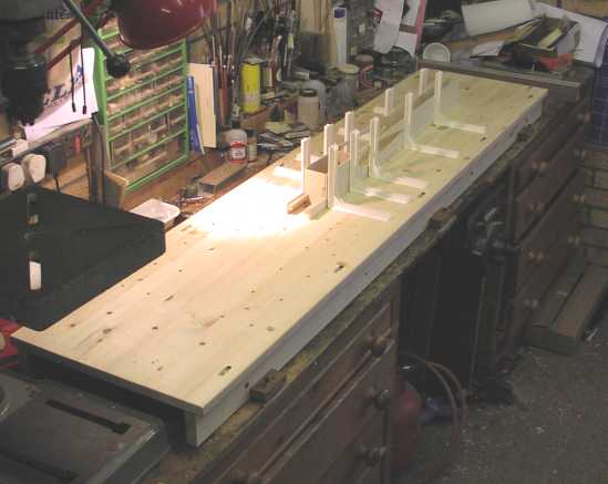
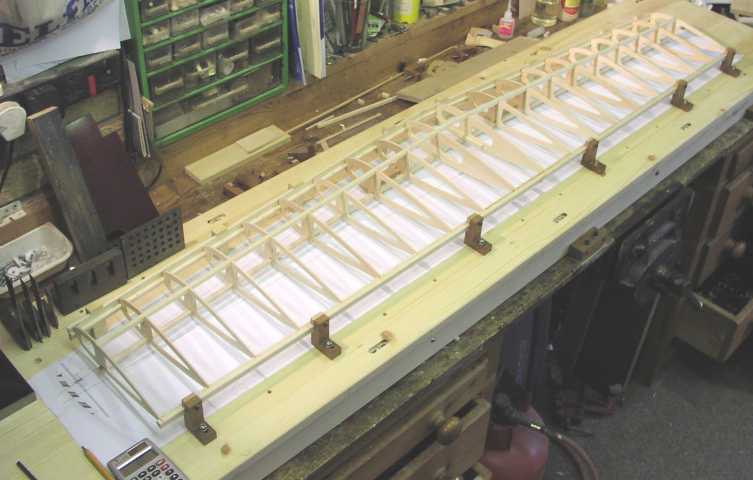
| A general view of the jig fitted to my bench. The model on it is a Nobler to give an idea of scale |
Details |
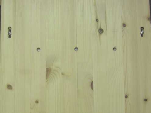 |
| The jig is made from strips of pine glued together. I bought this 1.8m X 0.4M X 20mm thick piece as a ready done item and was able to select the flatest, straightest one from a large rack of them. The long side bars are fixed to the top with screws in slots so that any differential shrinkage can be compensated for. |
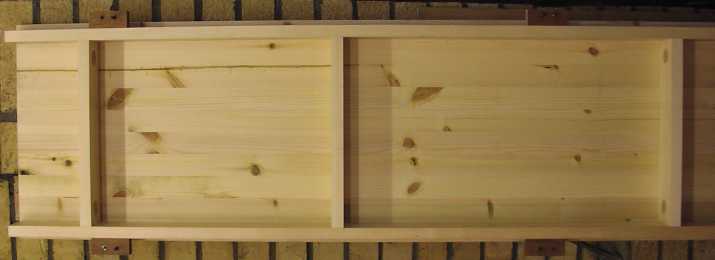 |
| The framework is made from 20mm thick X 65mm wide pine also selected for straightness. |
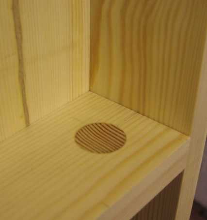 |
| The cross pieces are carefully planed square on the ends and checked for straightness. The 25mm dia dowel shown is to give the screws something other than end grain to screw into. |
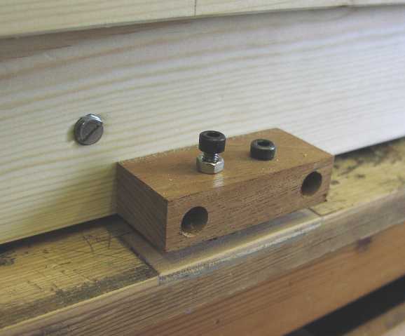 |
| The jig is mounted to the bench with 6 brackets each having 1 M5 cap head screw and nut screw acting as an adjustable foot and 1 M5 cap head screw acting as a hold down via some aluminimum plates with threaded inserts fitted. This enables me to ensure that the jig is truly flat and parallel along its length with no twist. Once the feet are adjusted I lock them with the lock nuts shown. I expect that I can remove and replace the unit with no need for readjustmentbut I would naturally check before any critical building work. |
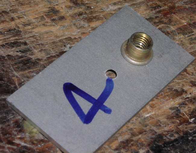 |
| The plates used to locate the jig are 16S.W.G. aluminimum fitted with a M5 threaded insert |
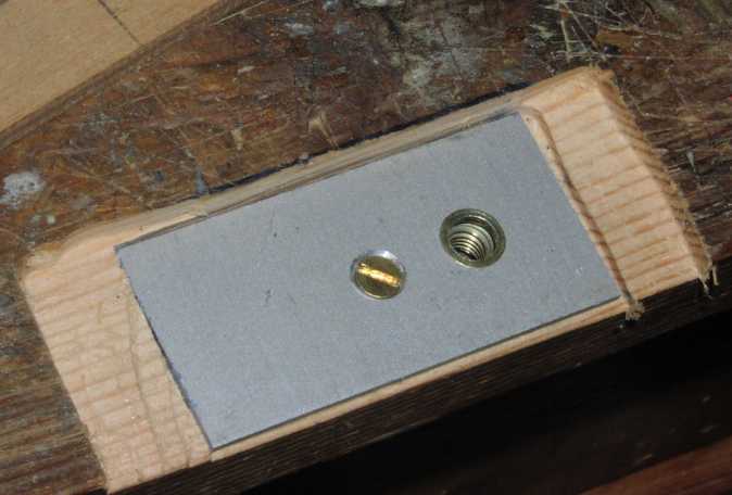 | The threaded plates are let into the bench as shown. |
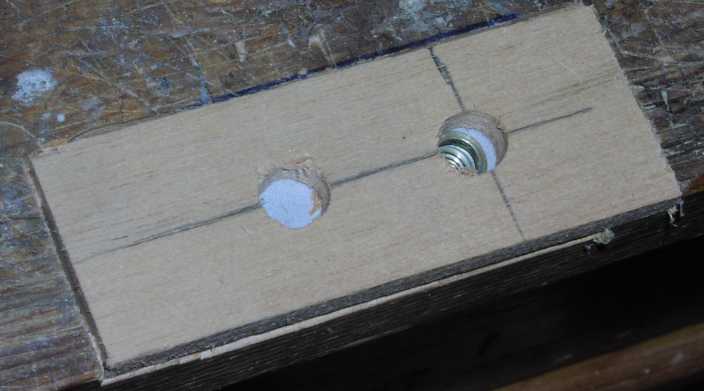 | and covered with ply top plates to protect them. I glued the plates and the top plates with epoxy to give a solid mount. |
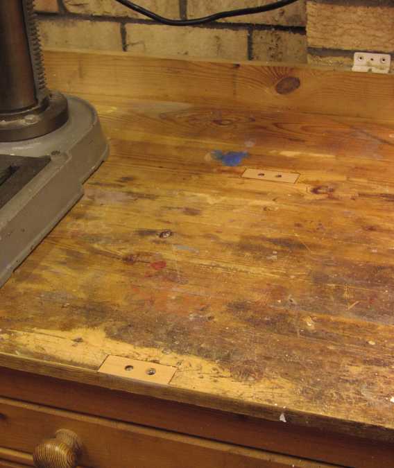 |
| There are 6 mounting let into my workbench. I covered the Aluminimum plates with ply to avoid blunting knives when cutting on the benchtop - a bad habit I can't be bothered to break |
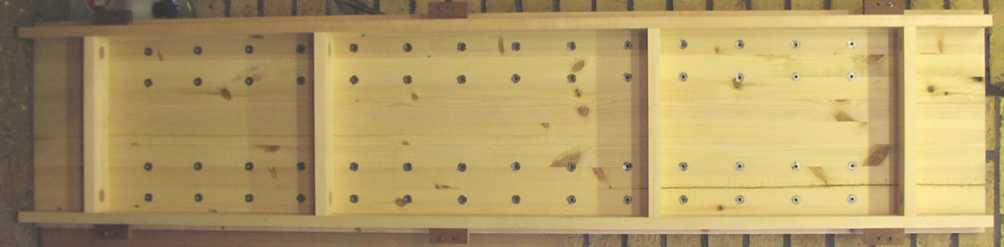 |
| The jig is fitted with 56 M5 threaded inserts to allow a range of add-ons to be clamped to the top. After much deliberation I chose a horizontal pitch of 4" and a front to back pitch of 160mm and 280mm about the centreline. |
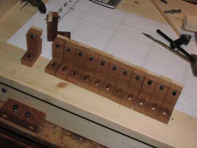 |
| I have made 14 trailing edge clamp blocks so far. These screw down to one of the rows of M5 holes |
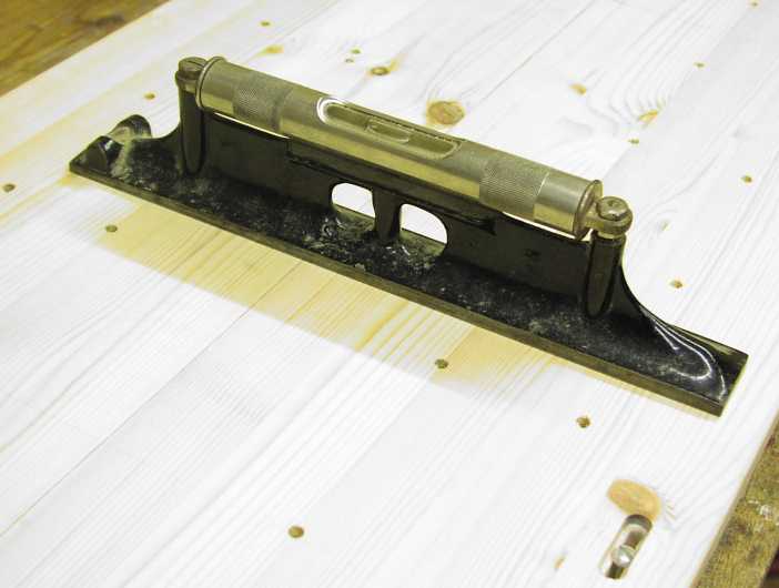 |
| This is the precision level I use to set the jig up on my bench. I found it in a junk shop some years ago and it is really intended for setting up machine tools so it is very accurate. |
 |
| The first wing to be built on this jig is my first Mo'Best, a superb large profile model by Larry Cunningham. |