| |
There is still a great deal of confusion about the use and adjustment of the movable rudder (actually, I never called it a "Rabe Rudder"). I thought the article in Stunt News Nov/Dec 2001 issue covered the subject well. It answered all the theoretical questions about how it works and described how to install and adjust one.
In conclusion:
Questions still arise. Without going into great detail of explanation about the use of the moving rudder, I thought I'd simply show some of my trim reasoning.
On its first flights, Snaggletooth had a bit of wobble in outside corners with these settings, otherwise it seemed OK. I figured it needed more right rudder on "down". I moved the pushrod in one hole on the rudder horn to make the rudder more sensitive. It would move more on both "up" and "down". The next flights proved the outside corners smooth now, with the rudder on "down" at eight units. I was also beginning to pick up a bit of slack on the first loop of the cloverleaf, an inside loop. I tried another hole inboard on the rudder horn and found no improvement in the outsides and a definite loss of tension in that cloverleaf first loop. The use of rudder movement inboard of rudder neutral may be appropriate and is theoretically correct to compensate for the outward yaw on inside, nose up, pitching maneuvers. It just happens that Snaggletooth doesn't like it. Theoretical correctness or no, practical trimming requires that observed deficiencies be addressed.
One possible solution to the problem would be to simply return the pushrod to the outside hole on the rudder horn and crank in more offset which would give less inboard rudder position on "up" and more outboard rudder position on "down". This would have certainly given an improvement in both inside and outside corners, but would result in more offset with elevator neutral than I wanted.
Another possibility would be to change the ratio of inboard movement to outboard movement so that the rudder would move less toward the inside and more toward the outside. This is accomplished by moving the elevator end of the rudder pushrod farther from the hinge line. If this is done to an extreme, the geometry might even cause a bit of outboard movement on "up" in addition to more outboard, or right, rudder on "down". I don't recommend this degree of asymmetry and have never had to use it in the past to obtain optimum trim. Snaggletooth, however, doesn't like any inboard movement of the rudder from the neutral rudder position on "up". It tends to weaken that first cloverleaf loop. Everywhere else is OK and I can "whip" that entry, but it is better to trim rather than to rely on "whipping".
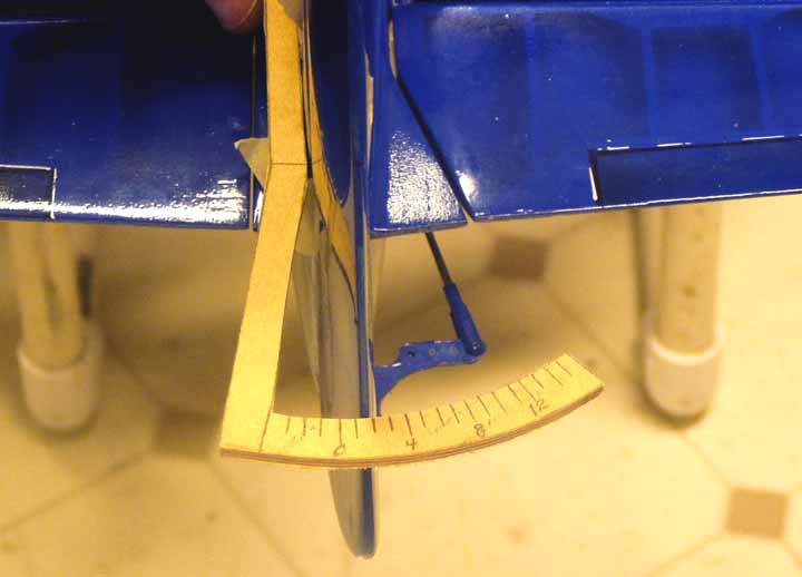
It should be noted that there are three separate adjustments possible with this simple device.
Overall rudder offset, rudder movement inboard on "up", and rudder movement outboard on "down" are individually adjustable without interfering with preferred adjustments of the other two.,br.
In the example above, I managed to reduce Inboard movement and increase outboard movement without changing the base rudder offset. Optimum adjustment of the movable rudder requires a thoughtful understanding of its capability and a template. Movable rudders added to airplanes without adjustment aren't likely to perform well.
Rudder offset is simply adjusted by the length of the pushrod. With all of the other possible adjustments this is just too simple. Base ruder offset should be whatever you would use if you built the airplane without an adjustable rudder.
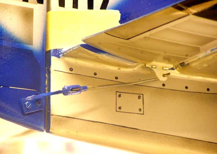
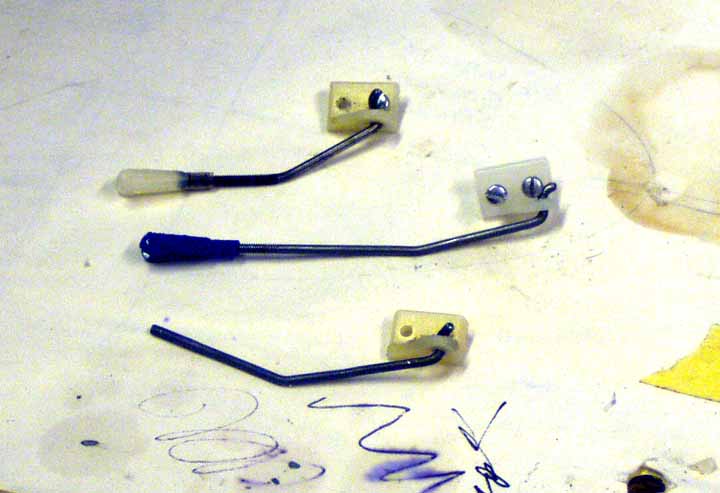
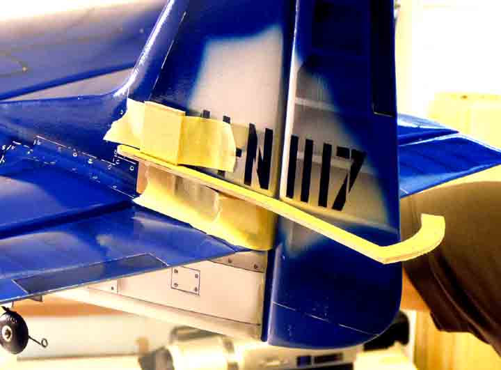
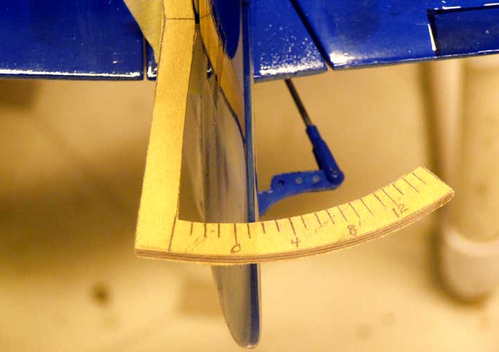
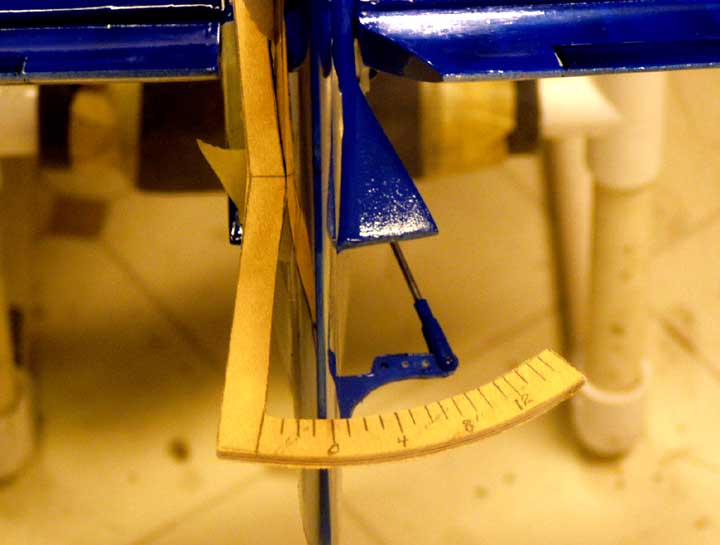
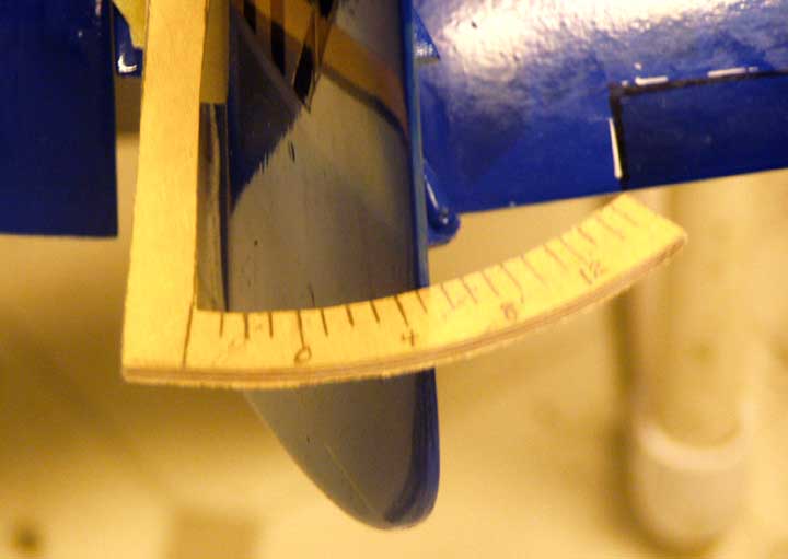
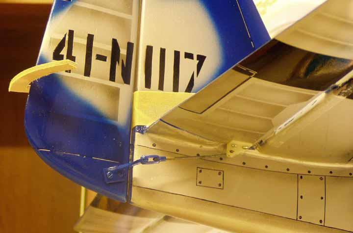
Rudder sensitivity, or total movement from one extreme to the other, is controlled by the holes on the rudder horn and, to a degree, by the "pickup" hole on the elevator horn. I try to keep the elevator "pickup" hole no farther from the bottom of the elevator than shown in the photos above and make sensitivity adjustments with the rudder horn. If the outside hole on the rudder horn is still too sensitive, make a new elevator horn with the "pickup" closer to the elevator surface.
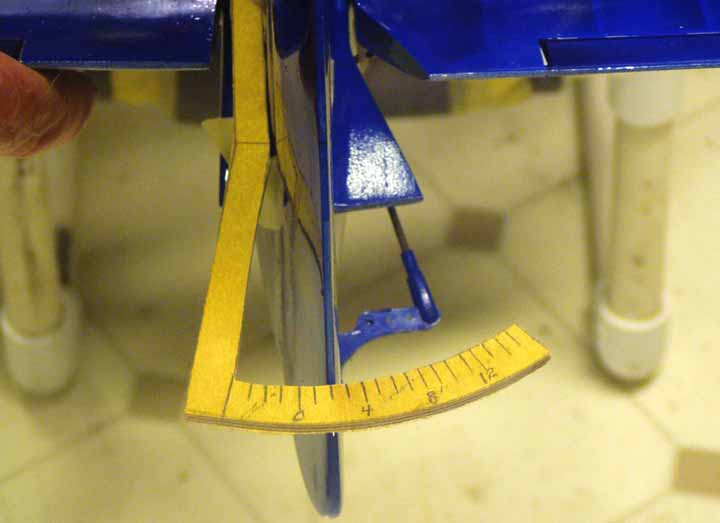
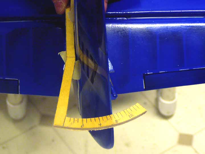
Rudder movement asymmetry is controlled by the fore and aft location of the "pickup" hole on the elevator horn. If the "pickup" is directly under the hinge line, the rudder will move equal amounts left and right from neutral offset. This is the theoretically correct location. With sensitivity adjustments, the rudder can be adjusted to remove all of the prop gyroscopic precession from the propeller which precesses the same on both inside and outside maneuvers, but in opposite directions. This was the original intent, and the way the first movable rudders were installed. In practice, it turned out that it was better to overcompensate for the inward yaw on outsides, to add a bit of outward yaw to improve line tension. In practice, it also became apparent that it was best not to remove all of the naturally occurring outward yaw from inside corners. By moving the "pickup" back from the hinge line, I was able to accommodate both of these actions by using more right rudder movement on outsides and less left rudder movement on insides. For most airplanes, this would be about 45 degrees behind the hinge line. I wouldn't use more asymmetry until I was very sure it is necessary. Remember, more rudder offset is another way to get more apparent asymmetry without changing the "pickup".
Now you know everything about how movable rudders work. The rest you learn by observing how the airplane flies in various maneuvers. With practice, you will get the hang of actually changing smoothness and line tension in various maneuvers and getting the best balance throughout the pattern. Trim technique was discussed in the Stunt News article. It might seem desirable to make the airplane yaw out strongly in all maneuvers but, again, that doesn't work very well. Excessive rudder induced yaw will give you more drag, and the drag can kill you in the wind. A balanced and moderate approach to trimming works best. Shoot for enough trim without overdoing it. The airplane should appear smooth and wobble free in corners and retain necessary minimum;m drag penetration in the verticals. Too much asymmetry is just as bad as too much movement. A light touch works best.
Al
This article was created by Mike Nelson from a submission by Al Rabe to the Stuka Stunt Forum
Further information on the Movable Rudder can be found on the PAMPA web site
Go back to Mike Nelsons Home Page
© 1997/8/9 2000.01.02.03.04.05.06.07.08 mike.nelson@machineconcepts.co.uk